Rockwell Automation 1794-ID2 U.MNL INCREMENTAL ENCODER User Manual
Page 49
4–5
Writing Configuration to and Reading Status from Your Module with a Remote I/O Adapter
Publication 1794ĆUM015B-EN-P - May 2001
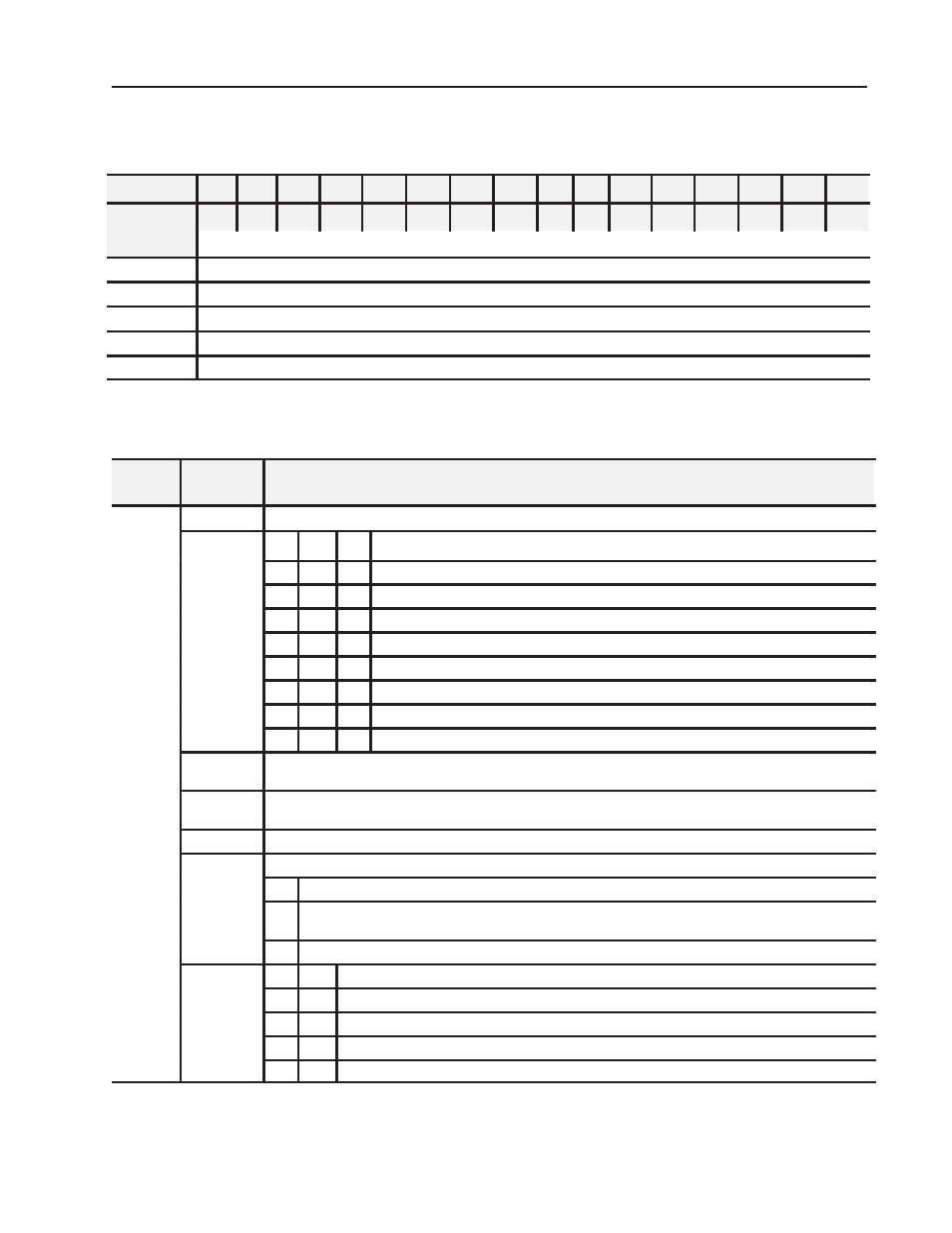
Block Transfer Write Word Assignments for the Incremental
Encoder Module
(Octal Bit)
⇒
17
16
15
14
13
12
11
10
07
06
05
04
03
02
01
00
Dec. Bit
⇒
15
14
13
12
11
10
09
08
07
06
05
04
03
02
01
00
Word
⇓
Write
0
Channel 0 Control Word - Sets the function of counter 0
1
Channel 1 Control Word - Sets the function of counter 1
2
Channel 0 Preset - value to load or compare with counter 0
3
Channel 1 Preset - value to load or compare with counter 1
4
Control Word 2 - Sets the filter function for both counters
Bit/Word Definitions for the Block Transfer Write Words for the
Incremental Encoder Module
Write
Word
Bit
Definition
Write
Word 0
0-15 (0-17) Channel 0 Control Word - Control word for setting the function of counter 0.
Word 0
Bits 00-02
02
01
00
Mode Selection bits
0
0
0
Counting on positive (rising) edge of input signal A. (Up/dwn counting determined by B.)
0
0
1
Quadrature encoder X1
0
1
0
Quadrature encoder X2
0
1
1
Quadrature encoder X4
1
0
0
Counting up on the positive edge of input signal A, and down on positive edge of input signal B.
1
0
1
No count function.
1
1
0
No count function.
1
1
1
No count function.
Bit 03
Preset (Reset) bit - A positive edge on this bit moves the value in Preset X to Counter X, independent of Preset
Enable. NOTE: To use Preset as Reset, use a count value of 0000 in the Preset value word.
Bit 04
Enable Z Preset bit - When this bit is set (1), a positive edge on Z preloads Counter X = Preset X, independent of
Cal Enable. NOTE: If Z is configured to do Store and Preset (Reset), the Store will occur first.
Bit 05
Count Enable bit - When this is set (1), the incremental encoder is enabled.
Bits 06-08
(06 10)
Calibration Control bits - bits 06, 07 and 08
(06-10)
06
Enable bit - When this bit is set (1), the counter can be calibrated.
07
Direction bit - When this bit set (1), calibration is performed in a negative direction; when reset (0), calibration
is performed in a positive direction.
08
Reset bit - Calibration is acknowledged and a new calibration is enabled on a positive edge on this bit.
Bits 09-10
(11 12)
10
09
Gate Control bits
(11-12)
0
0
No gate function on input G
0
1
Counting only if G is high (active)
1
0
Counting only if G is low (inactive)
1
1
The counter can be calibrated when G is high (active).