Rockwell Automation 1794-ID2 U.MNL INCREMENTAL ENCODER User Manual
Page 50
4–6
Writing Configuration to and Reading Status from Your Module with a Remote I/O Adapter
Publication 1794ĆUM015B-EN-P - May 2001
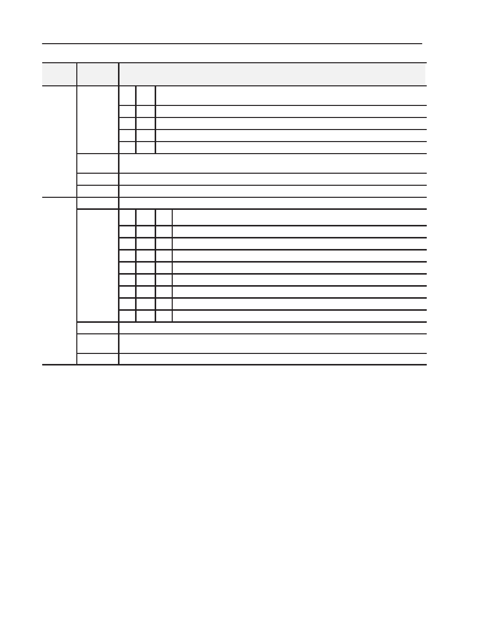
Definition
Bit
Write
Word
Write
Word 0
continued
Bits 11-12
(13-14)
12
11
Store Control bits - These bits will trigger a Store only if the channel Store status bit (L0 or L1) is
cleared (0).
continued
0
0
Save the counter value on the positive edge of Z (if Stored X = 0)
0
1
Save the counter value on the positive edge of G (if Stored X = 0)
1
0
Save the counter value on the negative edge of G (if Stored X = 0)
1
1
Save the counter value on the positive edge and negative edge of G (if Stored X = 0)
Bit 13 (15)
Rollover bit - When set (1), the counter counts up to the preset and then restarts at 0. If this bit is reset (0) (not
rollover), the rollover preset value = FFFF (hex = 65535 (decimal).
Bit 14 (16)
Store Reset bit - A positive edge on this bit resets Store X in Signals.
Bit 15 (17)
Preset Reset bit - A positive edge on this bit resets Preset Reached in Signals.
Write
Word 1
Channel 1 Control Word - Control word for setting the function of counter 1.
Word 1
Bits 00-02
02
01
00
Mode Selection bits
0
0
0
Counting on positive (rising) edge of input signal A. (Up/dwn counting determined by B.)
0
0
1
Quadrature encoder X1
0
1
0
Quadrature encoder X2
0
1
1
Quadrature encoder X4
1
0
0
Counting up on the positive edge of input signal A, and down on positive edge of input signal B.
1
0
1
No count function.
1
1
0
No count function.
1
1
1
No count function.
Bit 03
Preset bit - A positive edge on this bit moves the value in Preset X to Counter X, independent of Preset Enable.
Bit 04
Preset Enable bit - When this bit is set (1), a positive edge on Z preloads Counter X = Preset X, independent of Cal
Enable.
Bit 05
Count Enable bit - When this is set (1), the incremental encoder is counting.