Chapter summary – Rockwell Automation 1794-ID2 U.MNL INCREMENTAL ENCODER User Manual
Page 51
4–7
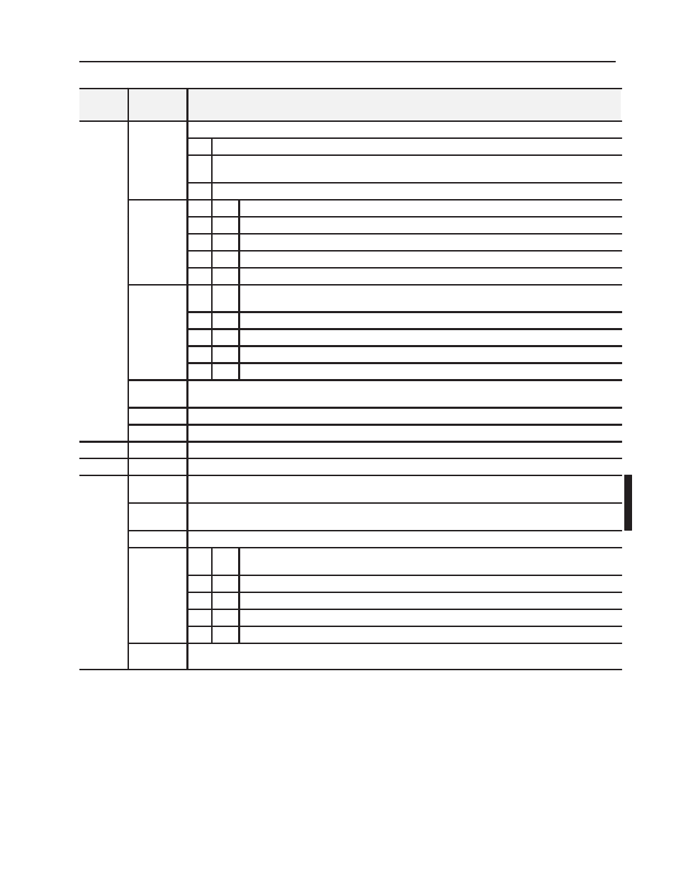
Writing Configuration to and Reading Status from Your Module with a Remote I/O Adapter
Publication 1794ĆUM015B-EN-P - May 2001
Definition
Bit
Write
Word
Word 1
continued
Bits 06-08
(06 10)
Calibration Control bits - bits 06, 07 and 08
continued
(06-10)
06
Enable bit - When this bit is set (1), the counter can be calibrated.
07
Direction bit - When this bit set (1), calibration is performed in a negative direction; when reset (0), calibration
is performed in a positive direction.
08
Reset bit - Calibration is acknowledged and a new calibration is enabled on a positive edge on this bit.
Bits 09-10
10
09
Gate Control bits
0
0
No gate function on input G
0
1
Counting only if G is high (active)
1
0
Counting only if G is low (inactive)
1
1
Calibration if G is high (active) and ???
Bits 11-12
(13-14)
12
11
Store Control bits - These bits will trigger a Store only if the channel Store status bit (L0 or L1) is
cleared (0).
0
0
Save the counter value on the positive edge of Z (if Store X = 0)
0
1
Save the counter value on the positive edge of G (if Store X = 0)
1
0
Save the counter value on the negative edge of G (if Store X = 0)
1
1
Save the counter value on the positive edge and negative edge of G (if Store X = 0)
Bit 13
Rollover bit - When set (1), the counter counts up to the preset and then restarts at 0. If this bit is reset (0) (not
rollover), the rollover preset value = FFFF (hex = 65535 (decimal).
Bit 14
Store Reset bit - A positive edge on this bit resets Store X in Signals.
Bit 15
Store Reset bit - A positive edge on this bit resets Preset Reached in Signals.
Word 2
Bits 00-15
Preset 0 - Value to load or compare with counter 0
Word 3
Bits 00-15
Preset 1 - Value to load or compare with counter 1
Word 4
Bit 00
Filter A0 enable - When this bit is set (1), anda counter 0 is in mode 000 (pulse counting), signal A0 is filtered by a
digital low pass filter with selectable filter constant.
Bit 01
Filter A1 enable - When this bit is set (1), anda counter 1 is in mode 000 (pulse counting), signal A1 is filtered by a
digital low pass filter with selectable filter constant.
Bit 02Ć07
Unused
Bits 08Ć09
(10Ć11)
09
(11)
08
(10)
Filter Constant bits - This constant is common to both counters.
0
0
73.5kHZ or minimum 0.007ms pulsewidth
0
1
37.8kHz or minimum 0.013ms pulsewidth
1
0
12.8kHz or minimum 0.04ms pulsewidth
1
1
1.2kHz or minimum 0.4ms pulsewidth
Bits 10Ć15
(12Ć17)
Reserved - set to 0
In this chapter, you learned how to configure your module’s features
and enter your data.
Chapter Summary