Rockwell Automation 1794-ID2 U.MNL INCREMENTAL ENCODER User Manual
Page 46
4–2
Writing Configuration to and Reading Status from Your Module with a Remote I/O Adapter
Publication 1794ĆUM015B-EN-P - May 2001
During normal operation, the processor transfers from 1 to 4 words
to the module when you program a BTW instruction to the module’s
address.
Read programming moves status and data from the frequency input
module to the processor’s data table in one I/O scan. The processor’s
user program initiates the request to transfer data from the
incremental encoder module to the processor.
The following read and write words and bit/word descriptions
describe the information written to and read from the incremental
encoder module. The module uses up to 8 words of input data and up
to 5 words of output data. Each word is composed of 16 bits.
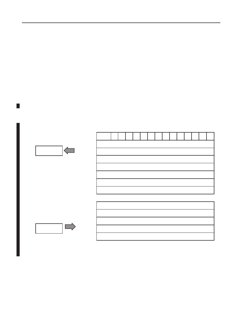
Incremental Encoder Module (1794ĆID2) Image Table Mapping
Module Image
I/O Image
Input Size
Output Size
0 to 5 Words
1 to 8 Words
G0 Z0
B0 A0
S1 S0
C1 C0
R
Z1
G1
A1
B1
PR0
PR1
Store 0 - Stored Counter Value on channel 0
Channel 0 - current counter value
Channel 1 - current counter value
Channel 0 - Counter word readback
Code for identification of software version
Channel 0 Control Word - Sets the function of counter 0
Channel 0 Preset - value to load or compare with counter 0
Preset 1 - value to load or compare with counter 1
Store 1 - Stored Counter Value on channel 1
Channel 1 - Counter word readback
Channel 1 Control Word - Sets the function of counter 1
Control Word 2 - Sets filter function for both counters
Reading Data From Your
Module
Mapping Data for the
Module