Rockwell Automation 1794-ID2 U.MNL INCREMENTAL ENCODER User Manual
Page 55
5–3
How Communication Takes Place and I/O Image Table Mapping with the DeviceNet Adapter
Publication 1794ĆUM015B-EN-P - May 2001
System throughput, from incremental encoder to backplane, is a
function of:
•
the configured minimum frequency sample time
•
the number of channels actually configured for connection to a
specific sensor (0 or 1)
You can set the minimum frequency time during module
configuration. The selection influences the sample data rate, thus
affecting system throughput.
The number of channels included in each input scan also affects
system throughput.
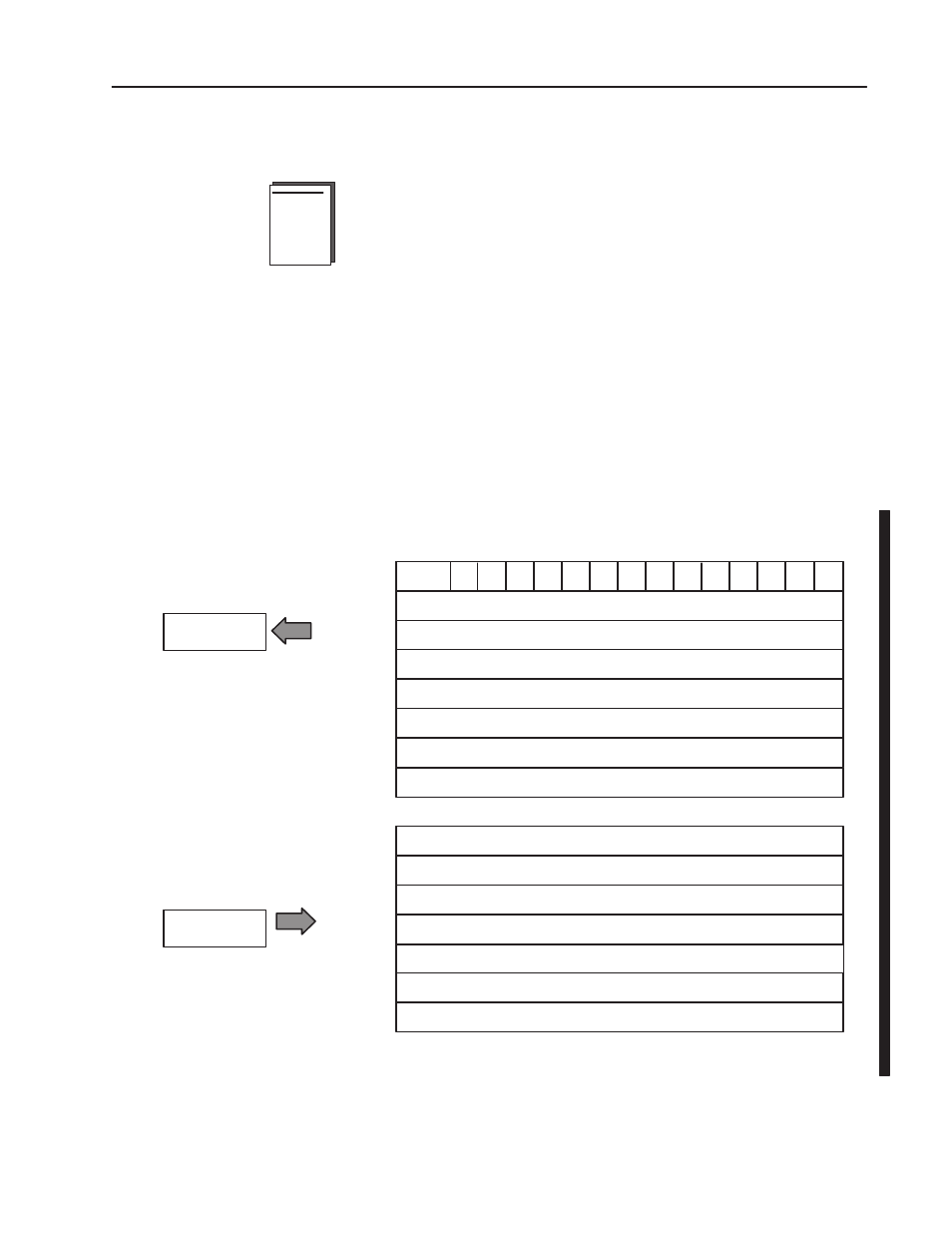
FLEX I/O incremental encoder module data table mapping is shown
below.
Incremental Encoder Module (1794ĆID2) Image Table Mapping
Module Image
I/O Image
Input Size
Output Size
0 to 7 Words
1 to 8 Words
G0 Z0
B0 A0
S1 S0
C1 C0
R
Z1
G1
A1
B1
PD0
PD1
Store 0 - SavedCounter Value on channel 0
Store 1 - SavedCounter Value on channel 1
Channel 0 - current counter value on channel 0
Channel 1 - current counter value on channel 1
Channel 0 - Counter wordreadback
Channel 1 - Counter wordreadback
Code for identification of software version
Channel 0 Control Word- sets the function of counter 0
Channel 1 Control Word- sets the function of counter 1
Channel 0 Preset - value to loador compare with counter 0
Channel 1 Preset - value to loador compare with counter 1
Not used
Not used
Control Word2 - Sets filter function for both channels
System Throughput
Mapping Data into the
Image Table