How the incremental encoder operates – Rockwell Automation 1794-ID2 U.MNL INCREMENTAL ENCODER User Manual
Page 16
1–4
Overview of the Incremental Encoder Module
Publication 1794ĆUM015B-EN-P - May 2001
The counter module handles up/down counting and detection of
selectable number of edges (X1, X2, X4) for incremental encoders
with 2 pulse trains, nominal 90
o
out of phase. The minimum stable
input condition is 2
µ
s.The following paragraphs detail operation of
the incremental encoder module.
Each of the 2 counters has a 16–bit counter register, a preset register
and a latch register.
Variables
Communication between the counter module and the control system
uses variables accessible in the control system program. These
variables include:
•
a counter register (Counter)
•
a preset register (PresetValue)
•
a latch register (LatchValue).
Signal registers and control words are used to set parameters for the
counter configuration. The control word sent to the incremental
encoder module can be read back to the control system, allowing
verification that one I/O scan been performed since the cycle has
been initiated.
Start Counting
The control bit CounterEnable enables counting. It must be set to 1
to enable counting and all other functions.
Selecting the incremental encoder and up/down counting
Depending on the incremental encoder, the module can be set in
different counter modes. The parameter is set using a 3 digit code in
write word 1 or 2 (depending on the channel) control word.
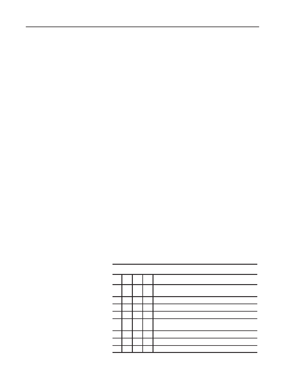
Mode Selection
Bit
02 01
00
Mode Selection bits
0
0
0
Counting on positive (rising) edge of input signal A. (Up/dwn
countingdetermined by B.)
0
0
1
Quadrature encoder X1
0
1
0
Quadrature encoder X2
0
1
1
Quadrature encoder X4
1
0
0
Counting up on the positive edge of input signal A, and down
on positive edge of input signal B.
1
0
1
No count function.
1
1
0
No count function.
1
1
1
No count function.
How the incremental
encoder Operates