Slcć5 programming, More – Rockwell Automation 1794-ID2 U.MNL INCREMENTAL ENCODER User Manual
Page 39
3–3
Programming Your Incremental Encoder Module
Publication 1794ĆUM015B-EN-P - May 2001
EN
BTR
BLOCK TRANSFER READ
Rack
Group
Slot
Control
001
0
0
N17:10
DN
Data File
Length
Continuous
N18:10
8
N
ER
EN
BLOCK TRANSFER WRITE
Rack
Group
Slot
Control
001
0
0
N17:0
DN
Data File
Length
Continuous
N18:0
4
N
ER
N17:10
15
S:1
15
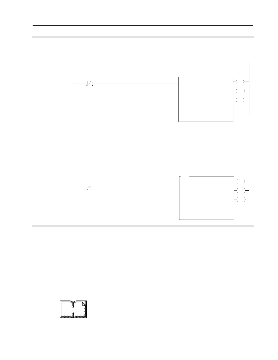
Rung 2:0
The ID2 module is located in rack 1, I/O group 0, slot 0. The integer control file starts at N17:0. The data sent by the
PLCĆ5 processor to the ID2 module starts at N18:0 and is 4 words long. At power up in RUN mode, or when the
processor is first switched from PROG to RUN, the user program enables a block transfer write to configure the module..
Rung 2:1
The ID2 module is located in rack 1, group 2, slot 0. The integer control file starts at N17:10,. The data obtained by the
PLCĆ5 processor from the ID2 module is placed in memory starting at N18:10 and is 8 words long. lThe program
continuously performs read block transfers to read data from the module.
ID2 BTR
Enable Bit
ID2 BTR
Control File
First scan of
ladder or SFC
ID2 BTW
Control File
PLCĆ5 Processor
Program Example
BTW
Module Type
Generic BT
Module Type
Generic BT
The SLC-5 programs (using the 1747-SN scanner) follow the same
logic as the PLC-5 family programs in the previous example.
Differences occur in the implementation of block transfers due to the
use of “M” files in the SLC system.
Configuration data for the FLEX I/O incremental encoder module
and the 1747-SN scanner must be in place before executing the
following programs. Chapter 4 contains information on module
configuration.
For more information on using the 1747-SN scanner module and
block transfer programming, refer to publication 1747-6.6, “Remote
I/O Scanner User Manual.”
More
SLCĆ5 Programming