Module indicators chapter summary – Rockwell Automation 1794-ID2 U.MNL INCREMENTAL ENCODER User Manual
Page 36
2–14
How to Install Your Incremental Encoder Module
Publication 1794ĆUM015B-EN-P - May 2001
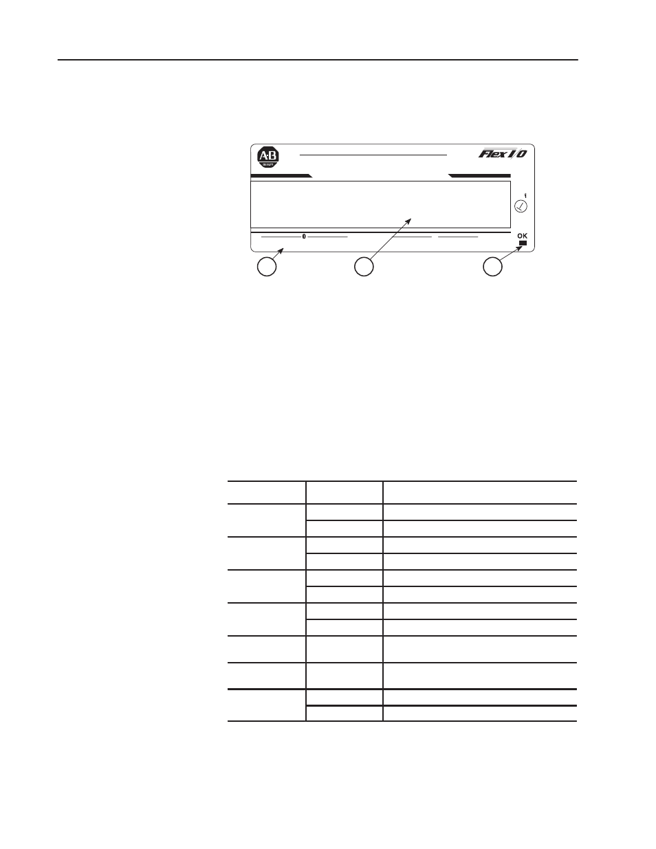
The incremental encoder module has one status indicator (PWR) that
is on when power is applied to the module, and one input status
indicator for each input (12 in all).
A
B
C
2 CH INCREMENTAL ENCODER MODULE
1794-ID2
A
B
Z
G
+
-
A
B
Z
G
+
-
AllenĆBradley
1
A = Power/status indicator – indicates power applied to module and
status of module.
B = Insertable label for writing individual I/O assignments.
C = Status Indicators –
A = Status of input A
B = Status of input B
Z = Status of input Z
G = Status of input G
+ = Positive count detected
– = Negative count detected
Indicator
Indication
Explanation
A
Yellow
Input A active
Off
Input A not active
B
Yellow
Input B active
Off
Input B not active
Z
Yellow
Input Z active
Off
Input Z not active
G
Yellow
Input G active
Off
Input G not active
+
Yellow
On when a positive pulse is detected; turns off
on negative pulse.
-
Yellow
On when a negative pulse is detected; turns off
on positive pulse.
OK
Red
Redduring initialization after power turnedon
Green
Green when initialization is completed
In this chapter, we told you how to install your incrementa encoder
module in an existing programmable controller system and how to
wire to the terminal base units.
Module Indicators
Chapter Summary