Wiring a processor restart lockout switch, Wiring a processor restart lockout switch -5, Momentary switch 14 – 24 gauge wire – Rockwell Automation 1747-ASB Remote I/O Adapter User Manual
Page 83
Publication 1747-UM006B-EN-P - June 2003
Installation and Wiring 5-5
Wiring a Processor Restart
Lockout Switch
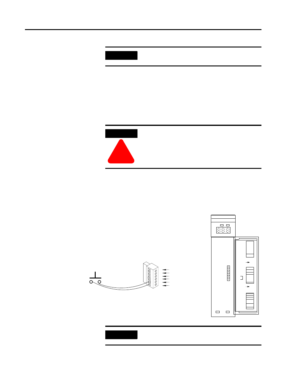
When processor restart lockout is enabled (SW3-2) and
communications are restored, the 1747-ASB module does not respond
to any type of communications, or communication commands until
terminals IN and RET are momentarily shorted together. This occurs
while the RIO scanner is attempting to communicate with the
1747-ASB module.
You must use a momentary switch (Class 1, Division 2) to short the
terminals together. The processor restart lockout is removed as soon
as the switch toggles back to the open circuit position.
A maximum of five feet of 14-24 gauge wire (solid or stranded) is
recommended to connect the switch to the terminal.
IMPORTANT
Do not connect anything to the NC (No Connect)
terminal.
ATTENTION
!
Cycling power on any 1747-ASB module chassis
removes the processor restart lockout condition by
re-initializing the 1747-ASB module.
Momentary Switch
14 – 24 gauge wire
ADAPTER
1 23
45
6
7
8
SW1
1 2
3
456
7
8
SW2
1 2
3
4
5
678
SW3
O
N
O
N
LINE 1
SHLD
LINE 2
NC
IN
RET
(MSB)
LOGICAL
RACK
(LSB)
LOGICAL
GROUP
BAUD
RATE
PRI/COMP
RSV
(MSB)
(LSB)
IMAGE
SIZE
HLS
PRL
RESP
LAST CHA
ADDR
MODE
SP MODE
KEY
1747–ASB
ST ATUS
COMM
F AUL T
LINE 1 (Blue wire)
SHLD (Shield wire)
LINE 2 (Clear wire)
NC (No Connect)
IN
RET
IMPORTANT
Do not connect anything to the NC (No Connect)
terminal.