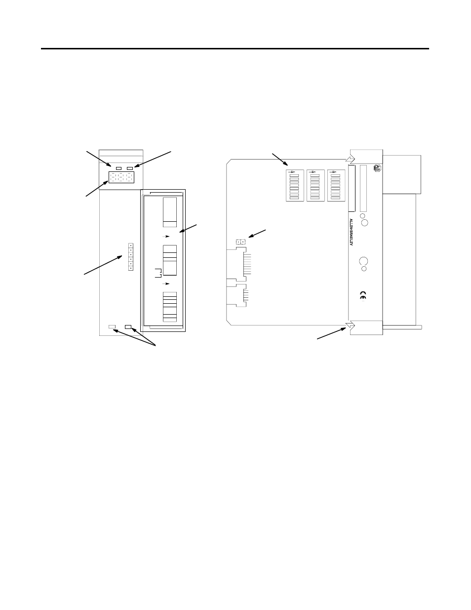
Hardware features, Status display and leds, Dip switches – Rockwell Automation 1747-ASB Remote I/O Adapter User Manual
Page 25: Comm led (green), Manufacturing test plug
Publication 1747-UM006B-EN-P - June 2003
Overview 1-11
Hardware Features
The 1747-ASB module's hardware features are highlighted below.
Detailed installation, operation, and troubleshooting information is
contained in chapters 5, 6, and 7.
Status Display and LEDs
The Status Display provides alphanumeric status of the 1747-ASB
module and RIO link. When combined with the COMM and FAULT
LEDs, they are very effective troubleshooting tools.
DIP Switches
The 1747-ASB module's three DIP switches allow you to configure the
following items:
•
Starting Logical Rack Number (Logical Rack) - is the
1747-ASB module's starting logical rack number in the scanner's
image.
•
Starting Logical Group Number (Logical Group) - is the
1747-ASB module's starting logical group number within the
scanner's image.
SLC 500
CA
T
SER
SERIAL
NO.
FRN
U
L
SA
ADAPTER
FAULT LED
(Red)
Door
Label
Status Display
Cable Tie Slots
DIP Switches
RIO Link and
Processor
Restart
Lockout
Connector
Self-Locking Tab
1 2
3
4
5
6
7
8
SW1
O
N
1 2
3
4
5
6
7
8
SW2
O
N
1 2
3
4
5
6
7
8
SW3
O
N
COMM LED
(Green)
IMPORT
ANT
:
INST
ALL
IN
SLOT
ZERO OF MODULAR CHASSIS ONL
Y
REMOTE I/O
ADAPTER
MODULE
F
AC
1M
MADE IN USA
CURRENT
REQUIREMENT
: 375mA
LISTED IND. CONT
. EQ.
FOR HAZ. LOC.
A196
CLASS 1, GROUPS
A,
B,
C
AND D, DIV
. 2
OPERA
TING
TEMPERA
TURE
CODE T3C
1 234
5
6
7
8
SW1
1 2
3
4
5
6
7
8
SW2
1 2
3
4
5
6
7
8
SW3
O
N
O
N
LINE 1
SHLD
LINE 2
NC
IN
RET
(MSB)
LOGICAL
RACK
(LSB)
LOGICAL
GROUP
BAUD
RATE
PRI/COMP
RSV
(MSB)
(LSB)
IMAGE
SIZE
HLS
PRL
RESP
LAST CHA
ADDR
MODE
SP MODE
KEY
1747–ASB
Manufacturing Test Plug
ST ATUS
COMM F AUL T
R
R