Rockwell Automation 1747-ASB Remote I/O Adapter User Manual
Page 110
Publication 1747-UM006B-EN-P - June 2003
8-6 Application Examples
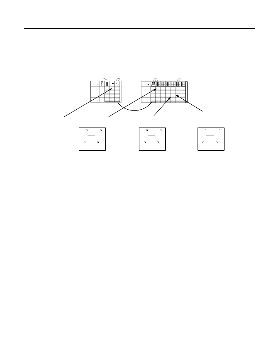
Shown below are examples of how the labels are filled out.
0
1
2
3
0
1
2
3
4
5
6
SLC 5/02
1746-OW8
1746-NIO4I
1747-SN
ASB
1746-OA16
1746-IA16
1746-IA16
1746-IA16
1746-OA16
1746-OA16
0 – 7
8 – 15
SN Slot
SN Word(s)
The switch is connected
to input 15.
Bulb 2 is connected
to output 12.
Bulb 1 is connected
to output 4.
3
0
The 0 –7 and 8–15 boxes are checked
because the module requires more than
one byte of image.
The SN Slot is 3 because that is the slot
the scanner occupies in the local SLC
chassis.
The SN Word is 0 because it is the SN
image word assigned to the IA16. These
values are determined by converting the
module’s logical rack and logical group
numbers (logical rack 0, G0) to the
corresponding SN words.
The 0 –7 and 8–15 boxes are checked
because the module requires more
than one byte of image.
The SN Slot is 3 because that is the
slot the scanner occupies in the local
SLC chassis.
The SN Word is 3 because it is the
SN image word assigned to the
OA16. The value is determined by
converting the module’s logical rack
and logical group numbers (logical
rack 0, G3) to the corresponding SN
word.
The 0 –7 and 8–15 boxes are
checked because the module
requires more than one byte of
image.
The SN Slot is 3 because that is the
slot the scanner occupies in the local
SLC chassis.
The SN Word is 4 because it is the
SN image word assigned to the
OA16. These values are determined
by converting the module’s logical
rack and logical group numbers
(logical rack 0, G4) to the
corresponding SN word.
Remote SLC
System
BT
Discrete
The meter is connected
to output 1.
0 – 7
8 – 15
SN Slot
SN Word(s)
3
3
Remote SLC
System
BT
Discrete
0 – 7
8 – 15
SN Slot
SN Word(s)
3
4
Remote SLC
System
BT
Discrete
✓
✓
✓
✓
✓
✓