Slot addressing -4, Slot addressing, Slot 1 – Rockwell Automation 1747-ASB Remote I/O Adapter User Manual
Page 40: Slot 2, Input image, Input image output image output image
Publication 1747-UM006B-EN-P - June 2003
3-4 Addressing
2-Slot Addressing
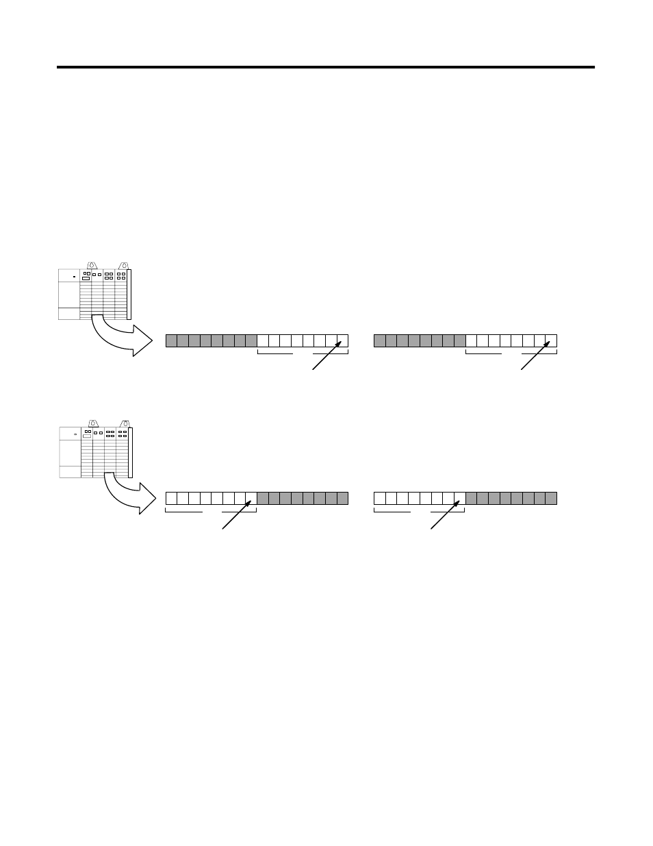
When the 1747-ASB module is configured for 2-slot addressing, the
processor addresses two chassis slots as one logical group. Each slot,
beginning with slot 1, is sequentially assigned one byte (8 bits) of the
1747-ASB module's input and output image. Each terminal on a
discrete I/O module installed in a slot is assigned a bit within the byte,
beginning with the least significant bit. 2-slot addressing is designed
to accommodate I/O modules whose image size is one byte or less.
Slot 1
Slot 1 is assigned to the low byte of the first logical
group of the 1747-ASB module ’s image, beginning
with bit 0 (the LSB).
Slot 1
1 5 1 4 1 3 1 2 11 1 0
9
8
7
6
5
4
3
2
1
0
Slot 2 is assigned to the high byte of the first
logical group of the 1747-ASB module ’s
image, beginning with bit 8 decimal, 10 octal.
Slot 2
1 5 1 4 1 3 1 2 11 1 0
9
8
7
6
5
4
3
2
1
0
Slot 2
Each terminal is assigned a bit,
beginning with the least significant bit.
Each terminal is assigned a bit,
beginning with the least significant bit.
group 0
group 0
Slot 1
1 5 1 4 1 3 1 2 11 1 0
9
8
7
6
5
4
3
2
1
0
Slot 2
1 5 1 4 1 3 1 2 11 1 0
9
8
7
6
5
4
3
2
1
0
Each terminal is assigned a bit,
beginning with the least significant bit.
group 0
group 0
Each terminal is assigned a bit,
beginning with the least significant bit.
Decimal
Octal
Decimal
Octal
7
0
7
0
7
0
7
0
10
10
10
10
17
17
17
17
Input Image
Input Image
Output Image
Output Image
Decimal
Octal
Decimal
Octal