Primary chassis complementary chassis, Logical rack 0 logical rack 1 – Rockwell Automation 1747-ASB Remote I/O Adapter User Manual
Page 62
Publication 1747-UM006B-EN-P - June 2003
4-8 Configuration
0
1
2
3
4
5
6
7
8
Slot Pair
1
2
3
4
I
I
I
I
O
O
O
O
O
O
O
O
O
I = Input Module
= Output Module
Input Image
Output Image
= unused
image
space
Slot 1
Slot 2
Slot 3
Slot 4
Slot 5
Slot 6
Slot 7
Slot 8
Slot 1
Slot 2
Slot 3
Slot 4
Slot 5
Slot 6
Slot 7
Slot 8
1
Slot Pair
2
3
4
Slot 1
Slot 2
Slot 3
Slot 4
Slot 5
Slot 6
Slot 7
Slot 8
Slot 1
Slot 2
Slot 3
Slot 4
Slot 5
Slot 6
Slot 7
Slot 8
1
2
3
4
Input Image
from Primary Chassis
Output Image
from Primary Chassis
Output Image
from Complementary Chassis
Slot 1
Slot 2
Slot 3
Slot 4
Slot 5
Slot 6
Slot 8
Slot 1
Slot 2
Slot 3
Slot 4
Slot 5
Slot 6
Slot 8
Slot 1
Slot 2
Slot 3
Slot 4
Slot 5
Slot 6
Slot 7
Slot 8
Slot 1
Slot 2
Slot 3
Slot 4
Slot 5
Slot 6
Slot 7
Slot 8
Slot 7
Slot 7
Input Image
from Complementary Chassis
Slot
Primary Chassis
Complementary Chassis
Slot 1
Slot 2
Slot 3
Slot 4
Slot 5
Slot 6
Slot 7
Slot 8
Slot 1
Slot 2
Slot 3
Slot 4
Slot 5
Slot 6
Slot 7
Slot 8
1
2
3
4
Slot 1
Slot 2
Slot 3
Slot 4
Slot 5
Slot 6
Slot 7
Slot 8
Slot 1
Slot 2
Slot 3
Slot 4
Slot 5
Slot 6
Slot 7
Slot 8
1
2
3
4
Slot 1
Slot 2
Slot 3
Slot 4
Slot 5
Slot 6
Slot 8
Slot 1
Slot 2
Slot 3
Slot 4
Slot 5
Slot 6
Slot 8
Slot 1
Slot 2
Slot 3
Slot 4
Slot 5
Slot 6
Slot 7
Slot 8
Slot 1
Slot 2
Slot 3
Slot 4
Slot 5
Slot 6
Slot 7
Slot 8
Slot 7
Slot 7
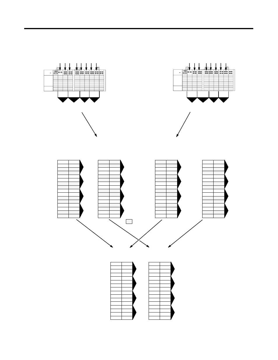
Primary Chassis I/O Image
Complementary Chassis I/O Image
Scanner’s I/O Image
1
2
3
4
Slot 1
Slot 2
Slot 3
Slot 4
Slot 5
Slot 6
Slot 8
Slot 1
Slot 2
Slot 3
Slot 4
Slot 5
Slot 6
Slot 8
Slot 1
Slot 2
Slot 3
Slot 4
Slot 5
Slot 6
Slot 7
Slot 8
Slot 1
Slot 2
Slot 3
Slot 4
Slot 5
Slot 6
Slot 7
Slot 8
Slot 7
Slot 7
Slot 1
Slot 2
Slot 3
Slot 4
Slot 5
Slot 6
Slot 7
Slot 8
Slot 1
Slot 2
Slot 3
Slot 4
Slot 5
Slot 6
Slot 7
Slot 8
1
2
3
4
Slot 1
Slot 2
Slot 3
Slot 4
Slot 5
Slot 6
Slot 7
Slot 8
Slot 1
Slot 2
Slot 3
Slot 4
Slot 5
Slot 6
Slot 7
Slot 8
Group 0
Group 2
Group 4
Group 6
Group 1
Group 3
Group 5
Group 7
Group 0
Group 2
Group 4
Group 6
Group 1
Group 3
Group 5
Group 7
Both images are overlapped in the
scanner. The overlapped image
appears where the primary chassis
image is configured to reside.
In this case, the primary chassis
image is configured as starting
logical rack 0 and starting logical
group 0.
I
I
I
I
Primary Chassis Configured As:
Logical Rack Number 0
Logical Group Number 0
Image Size (logical groups) 16
Addressing Mode 1/2-slot
Primary/Complementary Primary
Complementary Chassis Configured As:
Logical Rack Number 8 (decimal)
Logical Group Number 0
Image Size (logical groups) 16
Addressing Mode 1/2-slot
Primary/Complementary Complementary
Logical
Rack 0
Logical
Rack 1
0
7
8
15
7
0
10
17
Decimal
Octal
0
7
8
15
7
0
10
17
Decimal
Octal
0
7
8
15
7
0
10
17
Decimal
Octal
0
7
8
15
7
0
10
17
Decimal
Octal
0
7
8
15
7
0
10
17
Decimal
Octal
0
7
8
15
7
0
10
17
Decimal
Octal
Slot Pair
Slot Pair
Slot Pair
Slot Pair
Slot Pair
0
1
2
3
4
5
6
7
8
Slot Pair
1
2
3
4
Slot