Slc processor image, Slc processor input image, Slc processor output image – Rockwell Automation 1747-ASB Remote I/O Adapter User Manual
Page 114
Publication 1747-UM006B-EN-P - June 2003
8-10 Application Examples
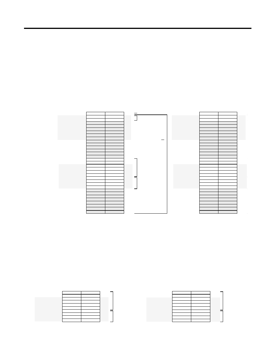
SLC Processor Image
Shown below are the SLC processor's input and output image. The
SLC processor image is comprised of the local I/O module images and
the RIO scanner images. The RIO scanner image size is four logical
racks. 1747-ASB module 1, 1747-ASB module 2, and the RediPANEL
are in the RIO scanner image.
1747-ASB Module 1 Configuration Details
Because 1747-ASB module 1's image crosses the logical rack boundary
of racks 1 and 2, 1747-ASB module 1 appears as two logical devices to
the RIO scanner.
Bit Number (Decimal)
Logical
Rack 1
0
7
8
15
Logical
Rack 0
Logical
Rack 2
Logical
Rack 3
SLC Processor Input Image
Local SLC Chassis
I:2.0
I:3.0
I:3.1
I:3.2
I:3.3
I:3.4
I:3.5
I:3.6
I:3.7
I:3.8
I:3.9
I:3.10
I:3.11
I:3.12
I:3.13
I:3.14
I:3.15
I:3.16
I:3.17
I:3.18
I:3.19
I:3.20
I:3.21
I:3.22
I:3.23
I:3.24
I:3.25
I:3.26
I:3.27
I:3.28
I:3.29
I:3.30
I:3.31
Group 0
Group 1
Group 2
Group 3
Group 4
Group 5
Group 6
Group 7
Group 0
Group 1
Group 2
Group 3
Group 4
Group 5
Group 6
Group 7
Group 0
Group 1
Group 2
Group 3
Group 4
Group 5
Group 6
Group 7
Group 0
Group 1
Group 2
Group 3
Group 4
Group 5
Group 6
Group 7
1747-ASB Module 2
1747-ASB Module 1
RediPANEL
IA8
IO12
IA16
NIO4I
NIO4I
NIO4I
NIO4I
IV32
IV32
IV32
IV32
Bit Number (Decimal)
Logical
Rack 1
0
7
8
15
Logical
Rack 0
Logical
Rack 2
Logical
Rack 3
SLC Processor Output Image
O:1.0
O:3.0
O:3.1
O:3.2
O:3.3
O:3.4
O:3.5
O:3.6
O:3.7
O:3.8
O:3.9
O:3.10
O:3.11
O:3.12
O:3.13
O:3.14
O:3.15
O:3.16
O:3.17
O:3.18
O:3.19
O:3.20
O:3.21
O:3.22
O:3.23
O:3.24
O:3.25
O:3.26
O:3.27
O:3.28
O:3.29
O:3.30
O:3.31
Group 0
Group 1
Group 2
Group 3
Group 4
Group 5
Group 6
Group 7
Group 0
Group 1
Group 2
Group 3
Group 4
Group 5
Group 6
Group 7
Group 0
Group 1
Group 2
Group 3
Group 4
Group 5
Group 6
Group 7
Group 0
Group 1
Group 2
Group 3
Group 4
Group 5
Group 6
Group 7
OW8
IO12
OA8
NIO4I
NIO4I
NIO4I
NIO4I
OV32
OV32
OV32
OV32
OB16
OB16
OA16
OA16
IA16
Scanner Image
Not Used
Not Used
Not Used
Not Used
Not Used
Not Used
Not Used
Not Used
Not Used
Not Used
Not Used
Not Used
Not Used
Not Used
Not Used
Not Used
Not Used
Not Used
Not Used
Not Used
Not Used
Not Used
Not Used
Not Used
Not Used
Not Used
Not Used
Not Used
Not Used
Not Used
Not Used
Not Used
Not Used
Not Used
Not Used
Not Used
Not Used
Not Used
Not Used
Not Used
Bit Number (Decimal)
0
7
8
15
Logical
Rack 2
SLC Processor Input Image
I:3.14
I:3.15
I:3.16
I:3.17
I:3.18
I:3.19
I:3.20
I:3.21
I:3.22
I:3.23
Group 6
Group 7
Group 0
Group 1
Group 2
Group 3
Group 4
Group 5
Group 6
Group 7
1747-ASB
Module 1
RediPANEL
NIO4I
NIO4I
NIO4I
NIO4I
IV32
IV32
IV32
IV32
Bit Number (Decimal)
0
7
8
15
Logical
Rack 2
SLC Processor Output Image
O:3.14
O:3.15
O:3.16
O:3.17
O:3.18
O:3.19
O:3.20
O:3.21
O:3.22
O:3.23
Group 6
Group 7
Group 0
Group 1
Group 2
Group 3
Group 4
Group 5
Group 6
Group 7
1747-ASB
Module 1
RediPANEL
NIO4I
NIO4I
NIO4I
NIO4I
OV32
OV32
OV32
OV32
OB16
OB16
OA16
OA16
Logical
Rack 1
Logical
Rack 1