Baud rate dip switch settings, Primary/complementary chassis (sw2-3) -5, Primary/complementary chassis (sw2-3) – Rockwell Automation 1747-ASB Remote I/O Adapter User Manual
Page 59: Primary, Complementary (default)
Publication 1747-UM006B-EN-P - June 2003
Configuration 4-5
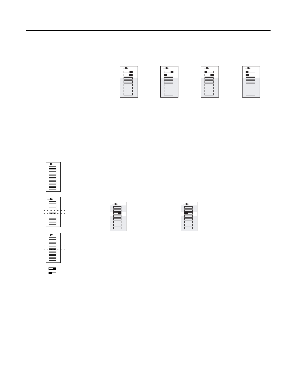
Baud Rate DIP Switch Settings
If the invalid switch setting is selected, a 1747-ASB module error
occurs.
Primary/Complementary Chassis (SW2-3)
SW2 switch 3 determines whether the 1747-ASB module appears to
the scanner as a primary or complementary chassis.
Primary/Complementary SLC Chassis DIP Switch Setting
If you are not using complementary I/O, all 1747-ASB modules
should be configured with SW2-3 in the default position. If a primary
chassis is configured and no complementary chassis exists, the
scanner wastes time trying to scan a complementary chassis that is not
there.
Complementary I/O allows two 1747-ASB modules to overlap their
input and output images, creating one image within the scanner, thus
maximizing image space. The combined image is located where the
primary image is configured to reside. Complementary I/O is very
useful when portions of your input and output images are unused.
SW2
57.6K
115.2K
230.4K
Invalid
SW2
SW2
SW2
4
1
23
5
6
7
8
O
N
4
1
23
5
6
7
8
O
N
4
1
23
5
6
7
8
O
N
4
1
23
5
6
7
8
O
N
SW2
Primary
4
1
23
5
6
7
8
O
N
SW2
Complementary (default)
4
1
23
5
6
7
8
O
N
4
1
2
3
456
7
8
SW1
S
W2
SW3
1
23
5
6
7
8
1
23
4
5
6
7
8
O
N
O
N
O
N
Specialty I/O Mode
I/O Module Keying
Addressing Mode
Last Chassis/PLC-3 Backup
Link Response
Processor Restart Lockout
Hold Last State
Baud Rate
Primary/Complementary Chassis
ASB Module Image Size
Logical Group Number
Logical Rack Number
ON
OFF
Reserved