Rockwell Automation 1771-DE Absolute Encoder Module User Manual User Manual
Page 36
Offset Programming
Chapter 5
5Ć5
Bit 7 is the loss-of-input-power bit. It is set when input power is lost; it
is reset when power is restored and bit 6 is reset.
Bit 6 is the write-data-valid bit. It is set at power-up and when the
processor changes from program mode to run mode; it is reset when the
module receives valid data in a block-transfer-write operation.
Bit 5 is the non-BCD offset flag. See the description of bit 0 and bit 1
below to identify the type of offset error.
Bit 4 is the non-BCD preset flag. It is set when a preset word is in
non-BCD format.
Bits 3 through 0 are a binary or hexadecimal code that indicates which
preset word is not in BCD format. Refer to Appendix D of the User’s
Manual for the value of these bits.
Bit 1 when set along with bit 5 identifies that the offset value is greater
than the number of encoder positions.
Bit 0 identifies which offset word is in non-BCD format when bit 5 is
also set.
- If bit 0 is set, the word containing the number of encoder positions is
in error.
- If bit 0 is reset, the word containing the offset value is in error.
The module identifies each non-BCD word in the order it finds them
(one at a time). Once you correct the format of one word, the
module continues to identify other non-BCD words.
Word 2 indicates the current position of the encoder, with the offset value,
in BCD.
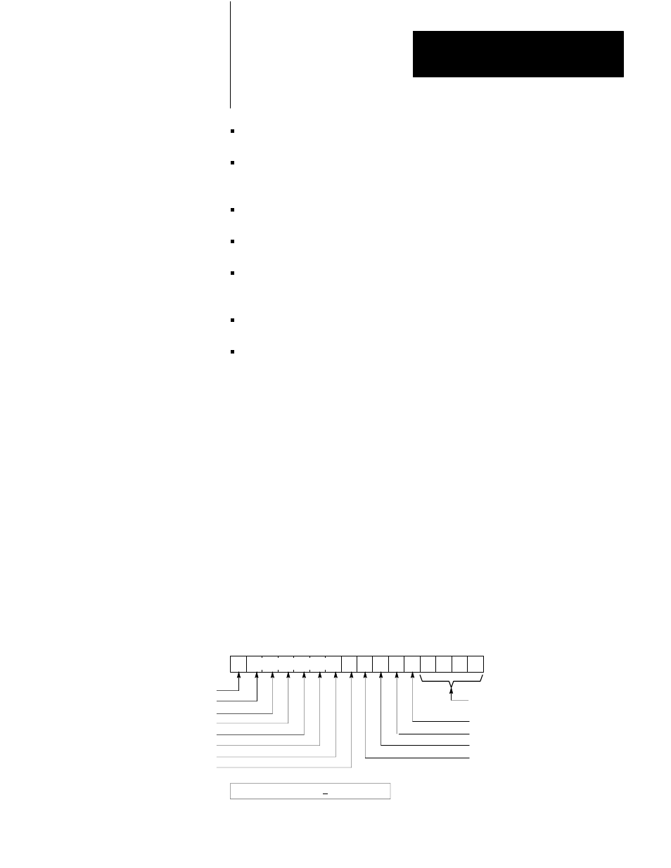
Figure 5.2
Format of BlockĆtransferĆread Data With Offset
17 16 15 14 13 12 11 10 07 06 05 04 03 02 01 00
Status of Outputs
Output 7
Output 6
Output 5
Output 4
Output 3
Output 2
Output 1
Output 0
Code indicating which preset or
offset word is in non-BCD format
Non-BCD preset flag
Non-BCD offset flag
Write-data-valid
Loss-of-input-power
Word 1
Word 2 Current Absolute Position + Offset (in BCD)
10216ĆI