Offset programming chapter 5 – Rockwell Automation 1771-DE Absolute Encoder Module User Manual User Manual
Page 35
Offset Programming
Chapter 5
5Ć4
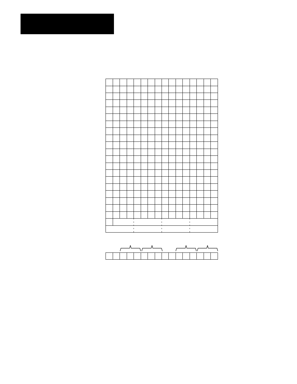
Figure 5.1
Format of BlockĆtransferĆwrite Data with Offset
17 16 15 14 13 12 11 10 07 06 05 04 03 02 01 00
OE ZT
<
Word #1
> =
<
> =
OE ZT
<
> =
<
> =
Control Word for
Outputs 0 and 1
2
Preset 0A
3
Preset 0B
4
Preset 1A
5
Preset 1B
OE ZT
<
6
> =
<
> =
OE ZT
<
> =
<
> =
Control Word for
Outputs 2 and 3
7
Preset 2A
8
Preset 2B
9
Preset 3A
10
Preset 3B
OE ZT
<
11
> =
<
> =
OE ZT
<
> =
<
> =
Control Word for
Outputs 4 and 5
12
Preset 4A
13
Preset 4B
14
Preset 5A
15
Preset 5B
OE ZT
<
16
> =
<
> =
OE ZT
<
> =
<
> =
Control Word for
Outputs 6 and 7
17
Preset 6A
18
Preset 6B
19
Preset 7A
20
Preset 7B
21
Offset Value
22
No. of Encoder Positions
S
A. Write-data words
B. Format of control
word #1
OE ZT
<
> =
<
> =
OE ZT
<
> =
<
> =
COM for
Preset 1B
COM for
Preset 1A
COM for
Preset 0B
COM for
Preset 0A
OE = Output Enable Bit
ZT = Zero Transition Bit
COM = Comparison Bit
S = Offset Sign Bit
10698ĆI
BlockĆtransferĆread Data with Offset
The upper byte of word 1 indicates the status of the eight outputs
controlled by the module. The module sets each bit when the
corresponding output is turned on.
The lower byte of word 1 (by bit) is:
- 20P PowerFlex DC Drive - Frame D Bimetal Thermostat (10 pages)
- 1336S_F_T_E_R F Frame Snubber Resistor Repl. (6 pages)
- 22-COMM PowerFlex 4-Class DSI (Drive Serial Interface) Network Communication Adapter (4 pages)
- 8-545 Plug In Solid State Relay (2 pages)
- 20-HIM-B1 PowerFlex 7-Class HIM Bezel (DPI) (4 pages)
- 100 Contactors with DC Coil (2 pages)
- 100 Contactors with DC Coil (1 page)
- 20P PowerFlex DC Drive - Frame D Switching Power Supply Circuit Board (6 pages)
- 140G-MTFx_MTHx_MTIx_MTKx Trip Unit Installation-140G-M (6 pages)
- 45BRD Analog Laser Sensor (4 pages)
- 20D Multi-Device Interface Option Board for PowerFlex 700S Drives (20 pages)
- 56RF RFID 18 mm Cylindrical Transceiver (2 pages)
- 42KC Miniature Rectangular: 5V DC Version (2 pages)
- 20P PowerFlex DC Drive - Frame A Switching Power Supply Circuit Board (16 pages)
- 21P-MISC-A-TP-2 Transition Tube Kit #C19-6/7 For PowerFlex 755 w/OEM Liquid Cooling Fr 6/7 Drive (2 pages)
- 42BT Background Suppression Sensor (3 pages)
- 42CB High Speed 18mm Cylindrical (4 pages)
- 140EX-JE2_JE3 Molded Case Circuit Breaker (4 pages)
- 140G-K-EAM1A Early Make Aux Contact for Rotary Handle Oper Mech-140G-K (1 page)
- 140G-K-EAM1A Early Make Aux Contact for Rotary Handle Oper Mech-140G-K (3 pages)
- 20-HIM-A6 PowerFlex (Human Interface Module) (74 pages)
- 42CF General Purpose 12mm Cylindrical (4 pages)
- 20D PowerFlex 700S Phase II Drive Frames 1...6 (80 pages)
- 140EX-HE1_HE2 Molded Case Circuit Breaker (6 pages)
- 140EX-HE1_HE2 Molded Case Circuit Breaker (4 pages)
- 20B PowerFlex 700 Custom Firmware - Pump Off (12 pages)
- 20-WIM-N4S DPI Wireless Interface Module (92 pages)
- 140U H-Frame Circuit Breaker Fixed and Adjustable Thermal Trip (2 pages)
- 140U H-Frame Circuit Breaker Fixed and Adjustable Thermal Trip (7 pages)
- 60-2619, 42JS Swivel/Tilt Mounting Bracket (1 page)
- 22A PowerFlex 4/40/400 Flange Mount (4 pages)
- 45MLA Controller Installation Instructions (16 pages)
- 20P PowerFlex DC Drive - Cooling Fan for Frame A Drives Above 73A at 230V 460V AC (6 pages)
- 42JS Series 7000 to 42JS VisiSight Replacement Kit (2 pages)
- 22A PowerFlex 4-Class HIM Bezel (DSI) (4 pages)
- 42CS Stainless Steel Photoelectric Sensors (4 pages)
- 20L-LL PowerFlex 700L Liquid-to-Liquid Heat Exchanger (40 pages)
- 20P PowerFlex DC Drive - Frame B SCR Modules (20 pages)
- 22B PowerFlex 40 Quick Start FRN 5.xx - 6.xx (161 pages)
- 22B PowerFlex 40 Quick Start FRN 5.xx - 6.xx (22 pages)
- 22F PowerFlex 4M Input RFI Filters (2 pages)
- 45LFM Capacitive Label Sensor (4 pages)
- 140G-Rx Installation Instruction-140G-R (2 pages)
- 140G-Rx Installation Instruction-140G-R (29 pages)
- 22C PowerFlex 400 AC Drive Quick Start - FRN 1-4.xx (28 pages)