Introducing the absolute encoder module chapter 2 – Rockwell Automation 1771-DE Absolute Encoder Module User Manual User Manual
Page 10
Introducing the Absolute Encoder Module
Chapter 2
2Ć5
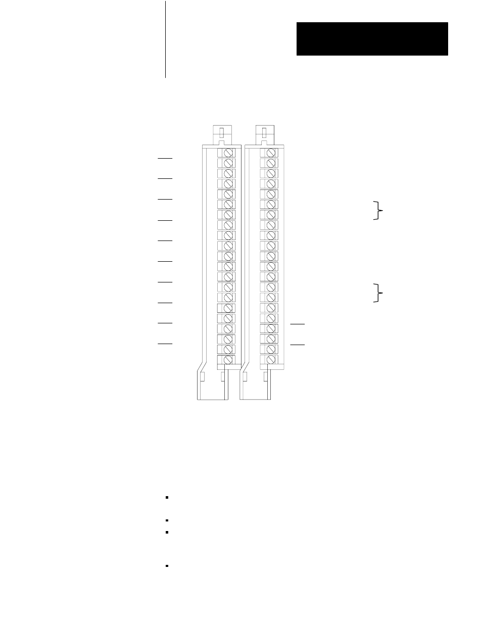
Figure 2.3
Terminal Identification
1
2
3
4
5
6
7
8
9
10
11
12
13
14
15
16
17
18
19
20
21
1
2
3
4
5
6
7
8
9
10
11
12
13
14
15
16
17
18
19
20
21
Output Supply (+5 to 24V dc)
Output 0
Output 1
Output 2
Output 3
Output Common (+5 to 24V dc)
Output Common (+5 to 24V dc)
Not Used
Output Supply (+5 to 24V dc)
Output 4
Output 5
Output 6
Output 7
Output Common (+5 to 24V dc)
Output Common (+5 to 24V dc)
Not Used
Bit 10
Bit 10 / Common
Bit 11
Bit 11 / Common
Input Common (+5V dc)
Bit 0
Bit 0 / Common
Bit 1
Bit 1 / Common
Bit 2
Bit 2 / Common
Bit 3
Bit 3 / Common
Bit 4
Bit 4 / Common
Bit 5
Bit 5 / Common
Bit 6
Bit 6 / Common
Bit 7
Bit 7 / Common
Bit 8
Bit 8 / Common
Bit 9
Bit 9 / Common
Input Supply
(+5V dc)
12832
Left
Wiring
Arm
Right
Wiring
Arm
For Outputs
0 - 3
For Outputs
4 - 7
Electrostatic discharge can damage integrated circuits or semiconductors
in this module if you touch backplane connector pins. It can also damage
the module when you set configuration plugs or switches inside the
module. Avoid electrostatic discharge by observing the following
precautions:
Touch a grounded object to discharge yourself before handling the
module.
Do not touch the backplane connector or connector pins.
When you configure and replace internal components, do not touch
other circuit components inside the module. If available, use a
static-safe workstation.
When not in use, keep the module in its static-shield bag.
Electrostatic Discharge