Rockwell Automation 1734-IT2I Thermocouple and RTD Input Module User Manual User Manual
Page 75
Publication 1734-UM004F-EN-E - December 2012
Configure Modules in RSLogix 5000 Software 65
2. From the top of the dialog, at Channel click on a push button to select a
channel, with the selected push button appearing pressed.
3. Make entries on the dialog, referring to the table for information on
how to complete entries for the channel indicated.
4. From the dialog, perform one of the following:
• Click a tab at the top of the dialog to continue making entries.
• Click OK to save changes and close the dialog.
• Cancel to return to default values.
• Click Apply to save changes you made on any of the dialogs and
continue to display the dialog, noting that you enable the Apply
button when you make changes to any of the dialogs.
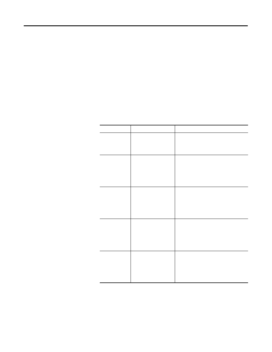
For This Value
Select
Comments
Channel
A push button to
correspond to a channel
such as 0, 1, and 2
Click a push button for a channel to show it
as pushed, which means the values you
enter on this dialog apply for the channel
you selected.
High High
-32,768...32,767
Select a value so that any value out of
range in this field causes a profile
validation error.
This value also appears in the HH slider on
this dialog.
Default is 32,767.
High
-32,768…32,767
Select a value so that any value out of
range in this field causes a profile
validation error.
This value also appears in the HI slider on
this dialog.
Default is 32,767.
Low
-32,768…32,767
Select a value so that any value out of
range in this field causes a profile
validation error.
This value also appears in the LO slider on
this dialog.
Default is -32,768.
Low Low
-32,768.…32,767
Select a value so that any value out of
range in this field causes a profile
validation error.
This value also appears in the LL slider on
this dialog.
Default is -32,768.