Install an i/o module, Warning – Rockwell Automation 1734-IT2I Thermocouple and RTD Input Module User Manual User Manual
Page 20
Publication 1734-UM004F-EN-E - December 2012
10 Install the Module
3. Press firmly to seat the mounting base on the DIN rail.
The mounting base snaps into place.
4. Repeat this procedure for the next mounting base assembly.
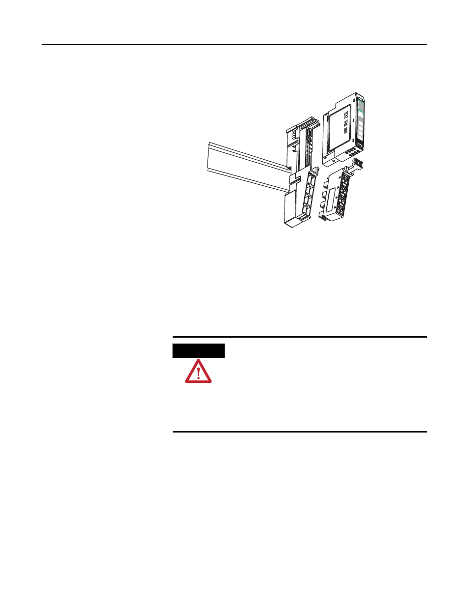
Install an I/O Module
Install the module before or after base installation. Make sure you correctly
keyed the mounting base before installing the module into the mounting base.
In addition, make sure you positioned the mounting base locking screw
horizontal, referenced to the base.
1. Using a bladed screwdriver, rotate the keyswitch on the mounting base
clockwise till the number required for the type of module you are
installing aligns with the notch in the base.
24VDC
Source
Output
Module
Sta
tus
Network
Sta
tus
1734
OB4E
NODE:
0
1
2
3
46003
WARNING
When you insert or remove the module while backplane power
is on, an electrical arc can occur. This could cause an explosion
in hazardous location installations.
Be sure that power is removed or the area is nonhazardous
before proceeding. Repeated electrical arcing causes excessive
wear to contacts on both the module and its mating connector.
Worn contacts may create electrical resistance that can affect
module operation.