Rockwell Automation 1734-IT2I Thermocouple and RTD Input Module User Manual User Manual
Page 13
Publication 1734-UM004F-EN-E - December 2012
About POINT I/O Modules 3
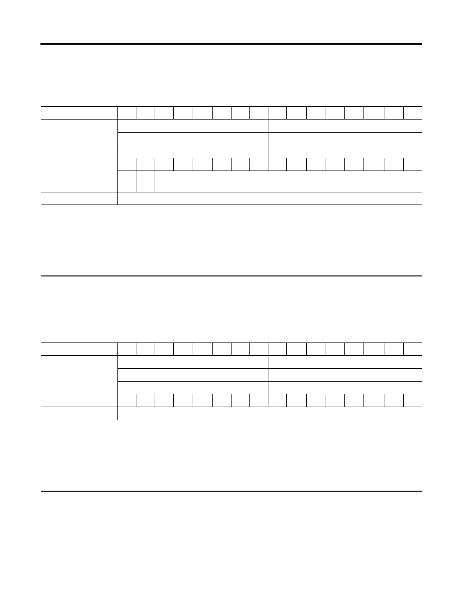
Default Data Map for the Thermocouple Input Module
(catalog number 1734-IT2I)
Default Data Map for the RTD Input Module
(catalog numbers 1734-IR2, and 1734-IR2E)
15
14
13
12
11
10
09
08
07
06
05
04
03
02
01
00
Produces (scanner Rx)
Input Channel 0 - High Byte
Input Channel 0 - Low Byte
Input Channel 1 - High Byte
Input Channel 1 - Low Byte
Status Byte for Channel 1
Status Byte for Channel 0
OR
UR
HHA LLA
HA
LA
CM
CF
OR
UR
HHA LLA
HA
LA
CM
CF
OR
UR
Cold Junction Temperature
(Selectable: Channel 0, Channel 1, or Average of both Channel 0 and 1)
Consumes (scanner Tx)
No consumed data
Where:
OR = Overrange; 0 = no error, 1 = fault (value went above selected range)
UR = Underrange; 0 = no error, 1 = fault (value went below selected range)
HHA = High/High Alarm; 0 = no error, 1 = fault (value went below setpoint
LLA = Low/Low Alarm; 0 = no error, 1 = fault (value went below setpoint
HA = High Alarm; 0 = no error, 1 = fault (value went below setpoint
LA = Low Alarm; 0 = no error, 1 = fault (value went below setpoint)
CM = Calibration Mode; 0 = normal, 1 = calibration mode
CF = Channel Fault status; 0 = no error, 1 = fault
15
14
13
12
11
10
09
08
07
06
05
04
03
02
01
00
Produces (scanner Rx)
Input Channel 0 - High Byte
Input Channel 0 - Low Byte
Input Channel 1 - High Byte
Input Channel 1 - Low Byte
Status Byte for Channel 1
Status Byte for Channel 0
OR
UR
HHA LLA
HA
LA
CM
CF
OR
UR
HHA LLA
HA
LA
CM
CF
Consumes (scanner Tx)
No consumed data
Where:
OR = Overrange; 0 = no error, 1 = fault (value went above selected range)
UR = Underrange; 0 = no error, 1 = fault (value went below selected range)
HHA = High/High Alarm; 0 = no error, 1 = fault (value went below setpoint)
LLA = Low/Low Alarm; 0 = no error, 1 = fault (value went below setpoint)
HA = High Alarm; 0 = no error, 1 = fault (value went below setpoint)
LA = Low Alarm; 0 = no error, 1 = fault (value went below setpoint)
CM = Calibration Mode; 0 = normal, 1 = calibration mode
CF = Channel Fault status; 0 = no error, 1 = fault