Using the drive indicator – Rockwell Automation 1756-HYD02 ControlLogix Hydraulic Servo Module User Manual
Page 80
80
Publication 1756-UM525A-EN-P - June 2003
Chapter 5 Troubleshooting the 1756-HYD02 Module
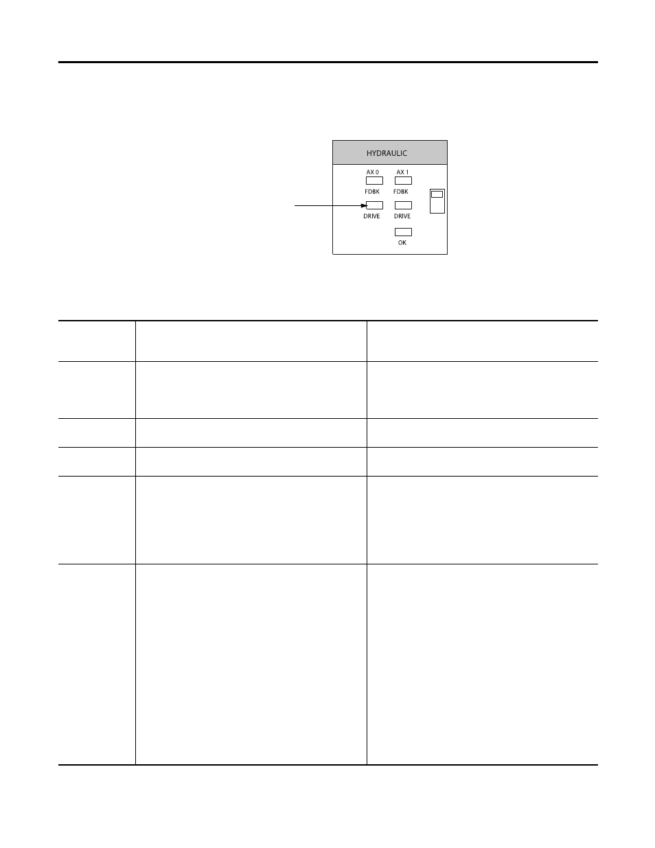
Using the DRIVE Indicator
The module’s DRIVE indicators are shown in Figure .
The table below explains the DRIVE indicator.
Drive
indicators
43454
DRIVE Indicator Displays
If the DRIVE
indicator
displays:
The module status is:
Take this action:
Off
One of the following:
• The axis is not used.
• The axis is a position-only axis type.
If the axis is being used and is not a position-only axis
type, make sure the module is configured, an axis tag has
been associated with the module, and the axis type is
servo.
Flashing green
light
The axis drive is in the normal disabled state.
None. The servo axis state can be changed by executing
motion instructions.
Steady green light The axis drive is in the normal enabled state.
None. The servo axis state can be changed by executing
motion instructions.
Flashing red light
The axis drive output is in the shutdown state.
Follow these steps:
1. Check for faults that may have generated this state.
2. Execute the Shutdown Reset motion instruction.
3. Resume normal operation.
Steady red light
The axis drive is faulted.
Follow these steps:
1. Check the drive status.
2. Clear the Drive Fault condition at the drive.
3. Clear the servo fault condition using the Motion Axis
Fault Reset instruction.
4. Resume normal operation.
5. Check the configuration for the Drive Fault.
• If configured to be normally open and there is no
voltage, this is the normal condition.
• If configured to be normally closed and 24V is
applied, this is the normal condition.