Using the fdbk indicator – Rockwell Automation 1756-HYD02 ControlLogix Hydraulic Servo Module User Manual
Page 79
Publication 1756-UM525A-EN-P - June 2003
79
Troubleshooting the 1756-HYD02 Module Chapter 5
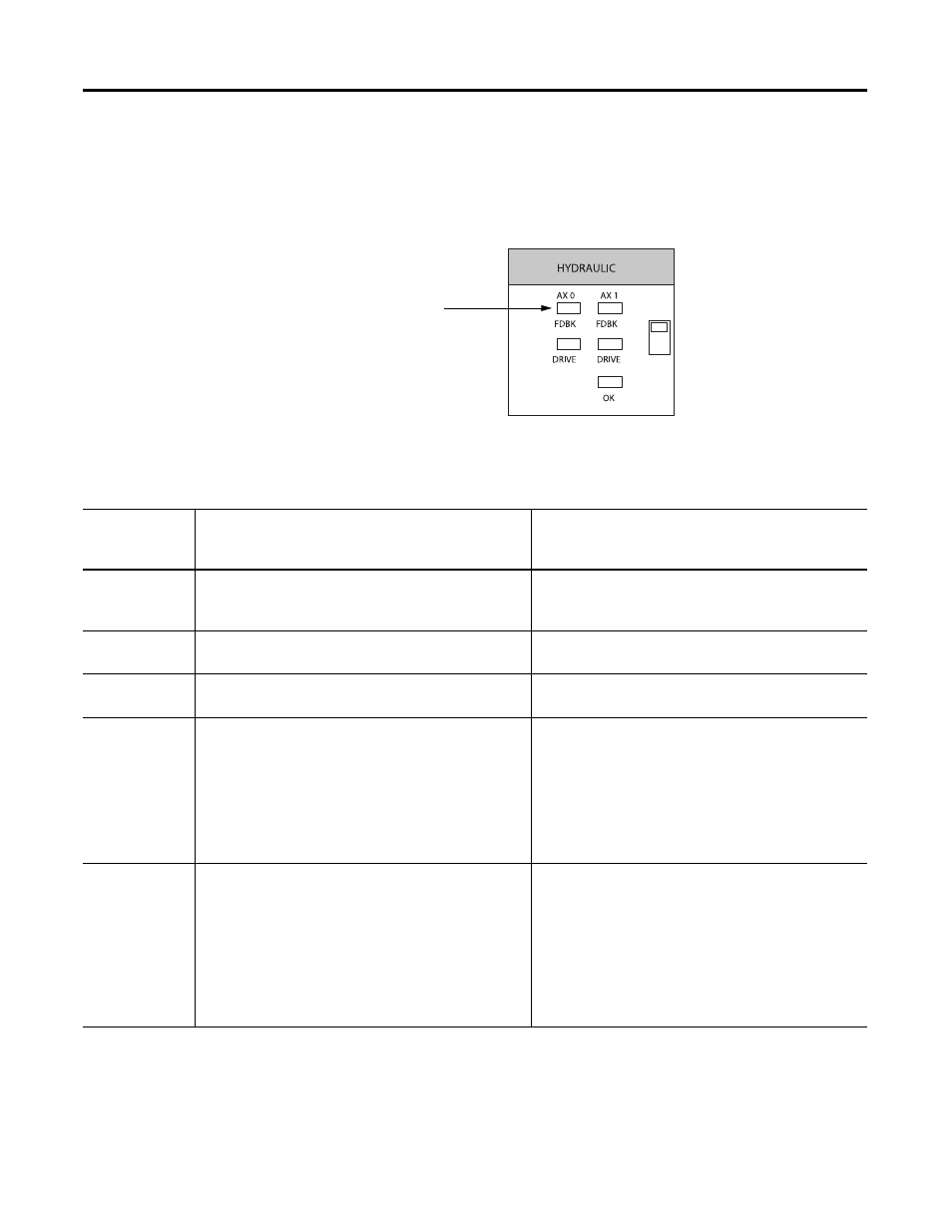
Using the FDBK Indicator
The module’s FDBK indicators are shown in Figure . Make sure that any
transducer used with the 1756-HYD02 module uses an external interrogation
signal.
The table below explains the FDBK indicators.
Feedback
indicators
43454
FDBK Indicator Displays
If the FDBK
indicator
displays:
The module status is:
Take this action:
Off
The axis is not used.
If you are using this axis, make sure the module is
configured and an axis tag has been associated with the
module.
Flashing green
light
The axis is in the normal servo loop inactive state.
None. The servo axis state can be changed by executing
motion instructions.
Steady green
light
The axis is in the normal servo loop active state.
None. The servo can may be changed by executing motion
instructions.
Flashing red light
The axis servo loop error tolerance has been exceeded.
Follow these steps:
1. Correct the source of the problem.
2. Clear the servo fault condition using the Motion Axis
Fault Reset instruction.
3. Resume normal operation.
Steady red light
An axis LDT feedback fault has occurred.
Follow these steps:
1. Correct the source of the problem by checking the LDT
and power connections.
2. Clear the servo fault condition using the Motion Axis
Fault Reset instruction.
3. Resume normal operation.