Connecting ldts to your hydraulic module – Rockwell Automation 1756-HYD02 ControlLogix Hydraulic Servo Module User Manual
Page 21
Publication 1756-UM525A-EN-P - June 2003
21
Installing the 1756-HYD02 Module Chapter 2
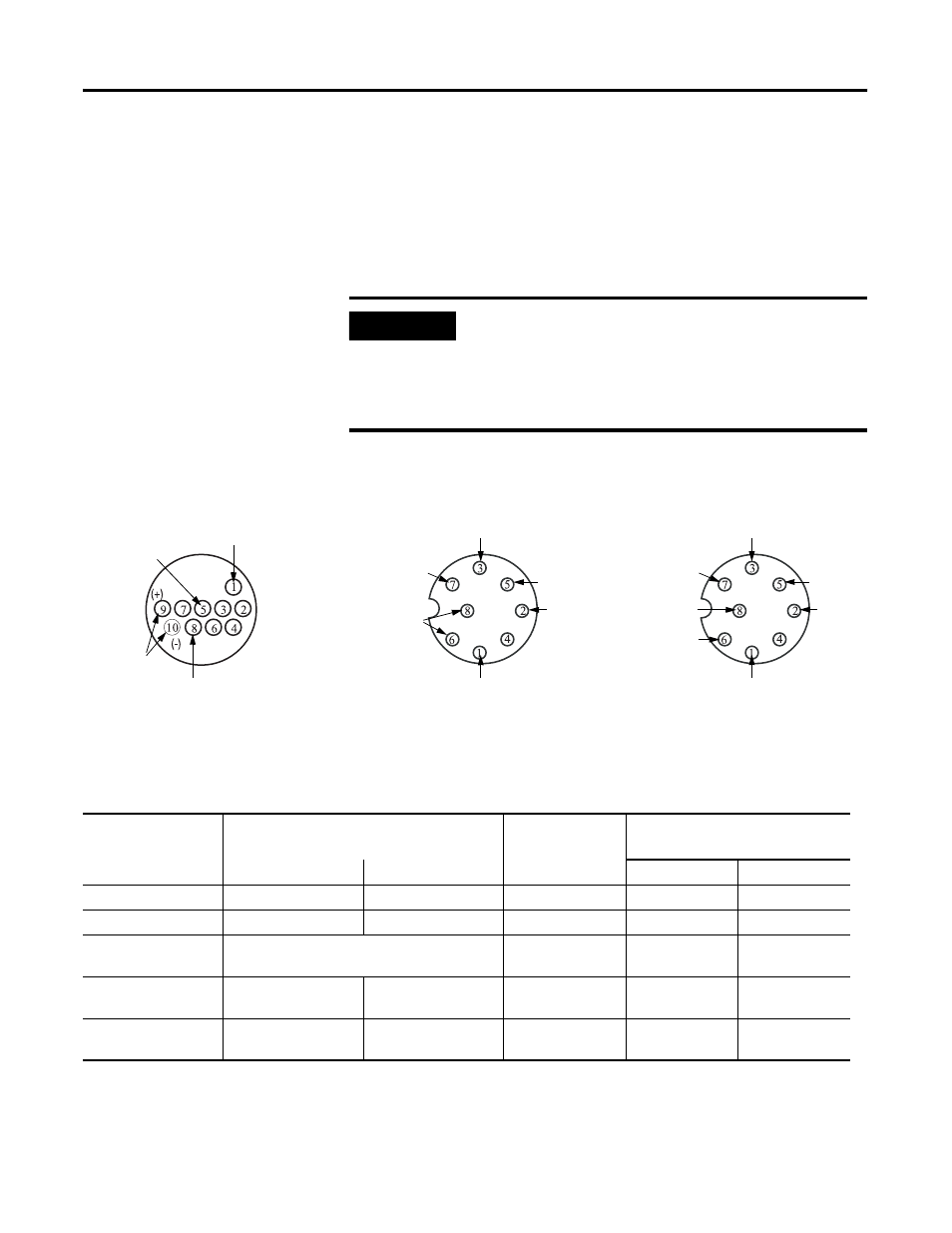
Connecting LDTs to Your Hydraulic Module
Because the number of LDTs that you can connect to your 1756-HYD02
module is continually changing, we cannot list all the available LDTs here.
Figure shows the connections for two example LDT types–Temposonic and
Balluff–that were available for connection to the 1756-HYD02 module at the
time of this printing.
Table lists the LDT connections.
IMPORTANT
Remember, there are other suppliers with compatible LDTs.
Before connecting an LDT to your module, we recommend you
make sure it is the best available LDT for your application.
Also, when wiring an LDT to your module, always follow the
LDT manufacturer’s instructions on making connections.
Temposonics II,
RPM or DPM
Balluff BTL type
43473
Interrogate
+/-12V dc
Output Pulse
Ground
Interrogate (+)
+24V
Pulse (+)
Output
Interrogate (-)
Pulse (-)
Output
Ground
Interrogate (+)
+15V
Pulse (+)
Output
Interrogate (-)
Pulse (-)
Output
Ground
-15V
24V Connections
+/- 15V Connections
No shield connections on these examples
LDT Connections for Fabricating Your Own LDT Cable
Function
(1)
1756-HYD02 RTB Wiring (Numbers below
represent terminal numbers)
Temposonics II
(2)
RPM or DPM
Balluff
BTL type
Channel 0
Channel 1
24V dc
+/- 15V dc
(+) Interrogate
26
25
9 - Yellow
1 - Yellow
1 - Yellow
(-) Interrogate
28
27
10 - Green
3 - Pink
3 - Pink
Power Supply
N/A
5 - Red (+/-12V)
7 - Brown (+24V)
7 - Brown (+15V)
8 - White (-15V)
Ground
34
33
1 - White
6 - Blue
8 - White
6 - Blue
Output Pulse
30 (+)
32 (-)
29 (+)
31 (-)
8 - Purple
2 - Gray (+)
5 - Green (-)
2 - Gray (+)
5 - Green (-)
(1)
(+) and (-) wires of the same function should be a twisted pair within the cable.
(2)
Do not connect to pins 2, 3, 4, 6 or 7