Wire an armorpoint i/o adapter, Wire the adapter, Chapter summary – Rockwell Automation 1738-AENT, Series B ArmorPOINT I/O Dual Port EtherNet/IP Adapters User Manual User Manual
Page 22
12
Rockwell Automation Publication 1738-UM005A-EN-P - July 2013
Chapter 2 Install Your ArmorPOINT I/O Adapter
Wire the Adapter
Wire an ArmorPOINT I/O Adapter
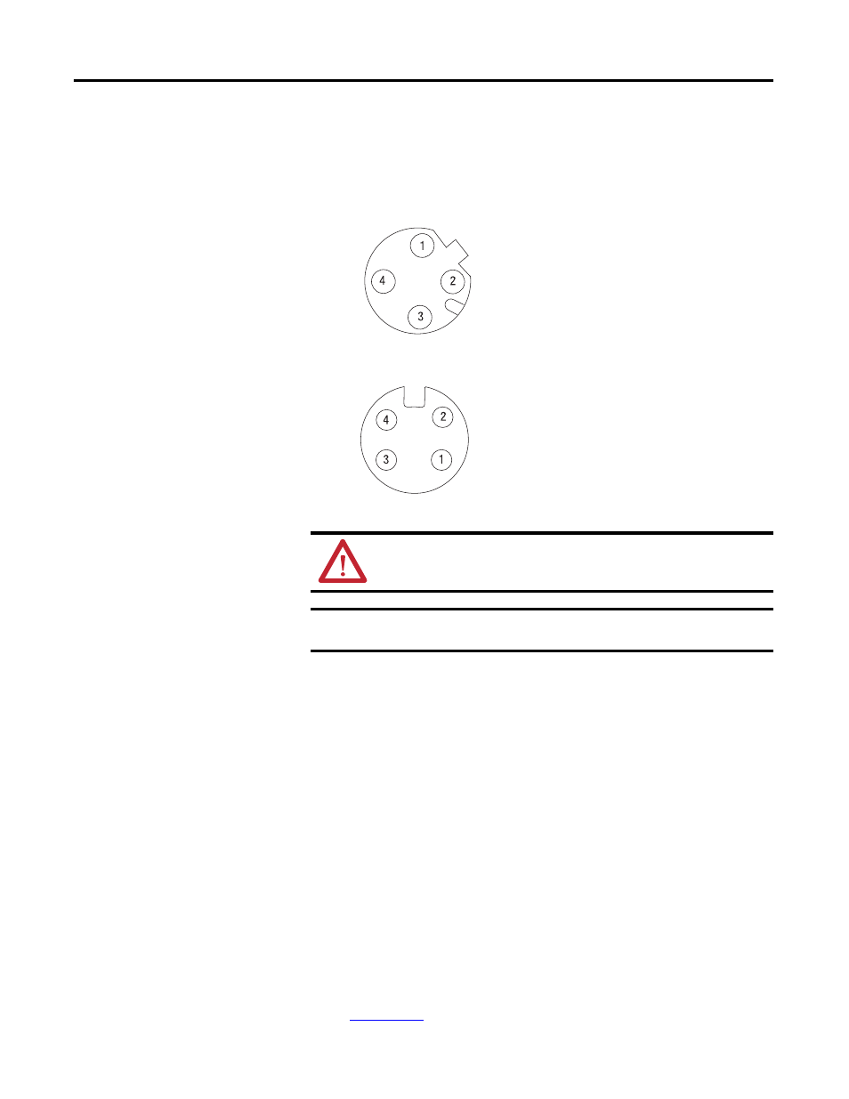
Refer to the following illustration to wire the adapter
EtherNet/IP Connectors
Auxiliary Power Connector
(1)
Chapter Summary
In this chapter, you learned how to install and wire your EtherNet/IP adapter.
The following chapter describes how to configure the adapter to communicate on
your EtherNet/IP network by providing an IP address, gateway address, and
Subnet mask.
ATTENTION: Make sure all connectors and caps are securely tightened
to properly seal the connections against leaks and maintain IP enclosure
type requirements.
IMPORTANT
Analog modules have earth grounded metal rings. This should be
considered when choosing shielded cables and grounding techniques.
(1) Auxiliary power cable: standard cordset (single-ended), for example Allen-Bradley part number 889N-F4AFC-6F or 889N-R4AFC-
6F; or standard patchcord (double-ended), for example, Allen-Bradley part number 889N-F4AFNU-6F or 889N-F4AFNV-6F. Refer to
publication
r more information.
(view into connector)
Pin 1 - Tx +
Pin 2 - Rx +
Pin 3 - Tx -
Pin 4 - Rx -
M12 Female in Connector
43765
43587
Mini Style 4-Pin in Male Connector
(view into connector)
Pin 1 - User Power +
Pin 2 - Adapter Power +
Pin 3 - Adapter Power -
Pin 4 - User Power -