Armature bridge components – Rockwell Automation 1395 DC Drive, 800-1250 Hp, FRN 5.XX-9.30 User Manual
Page 16
Chapter 2
Hardware Description
2-3
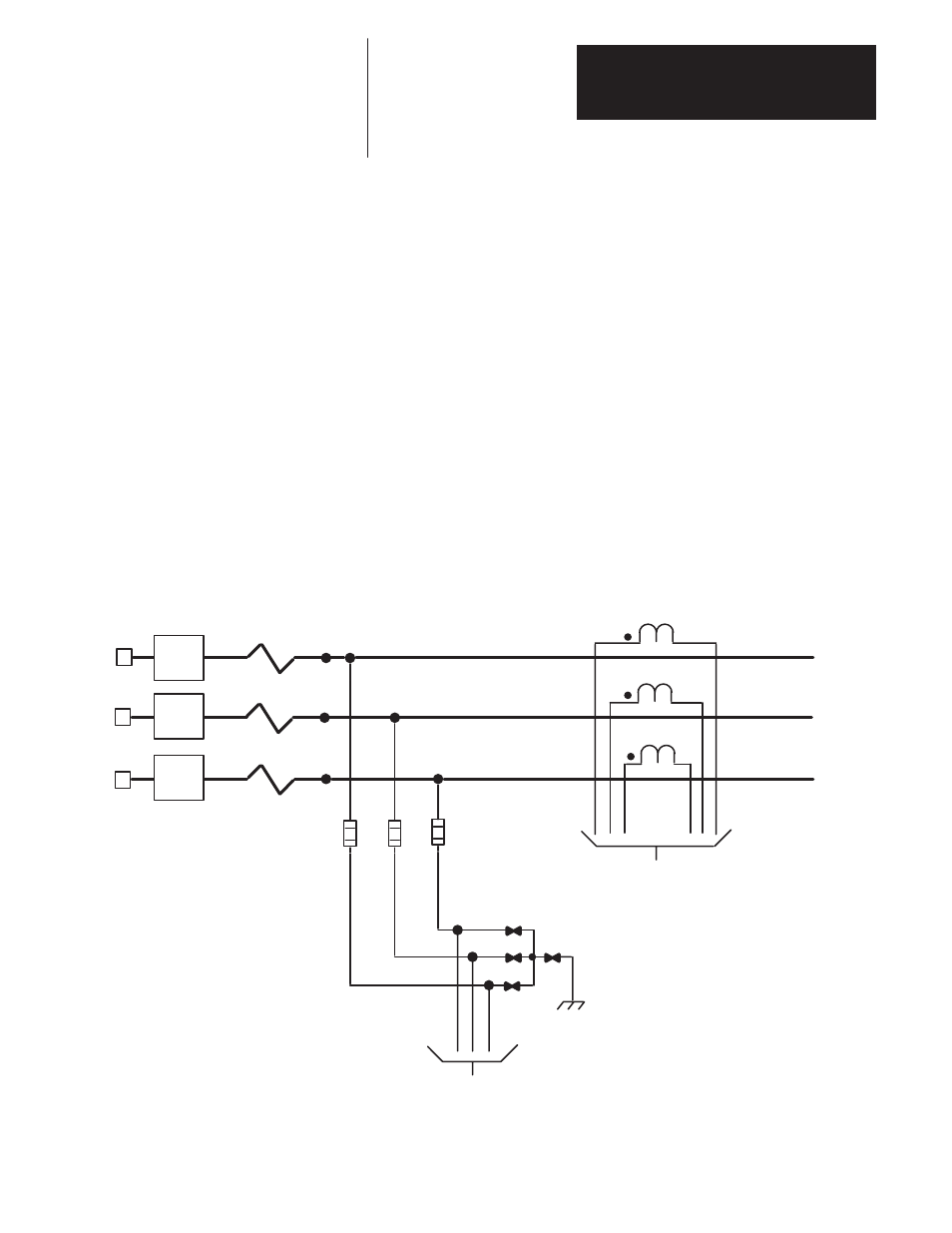
Armature Bridge Components
A general description of the components in the armature bridge (Figures
2.2 and 2.3) and their operation is detailed here:
AC Line Reactor – When connecting the drive directly to the main
distribution system an AC line reactor must be used to guard against
system disturbance.
When an isolation transformer matched to the unit rating is used, an AC
line reactor is not required.
Synchronization – The three-phase input to the drive is tapped and fused
using fuses 11F, 12F and 13F (Fig. 2.2) and enters the feedback board.
The feedback board scales down the voltage before being sent to the power
stage interface where it is used to develop the synchronizing information to
be used by the Main Control Board.
AC Current Feedback – Current Transformers ACT-1, ACT-2 and
ACT-3 (Figure 2.2) are used to provide current feedback information to the
feedback board. The feedback board rectifies the three-phase feedback and
scales the DC voltage before being sent to the power stage interface. The
DC voltage representing the current feedback is passed directly through the
power stage interface and sent to the main control board.
Figure 2.2
Armature Bridge Components (INPUT)
To Feedback Board
Figure 2.5
CB-1
L1
L2
L3
11F
12F
13F
ACT-1
ACT-3
4 MOV
ACT-2
To Feedback Board
Figure 2.5
5 MOV
6 MOV
7 MOV
ЗЗЗ
ЗЗЗ
ЗЗЗ
AC Line
Reactor
ЗЗЗ
ЗЗЗ
ЗЗЗ
ЗЗЗ
ЗЗЗ
Surge Suppression – The Surge Suppressor Network (4 MOV, 5MOV,
6MOV and 7MOV Fig. 2.2) protects the Feedback Board from high
voltage line spikes and line surges.