Rockwell Automation 193-DNENCATR EtherNet/IP Communications Auxiliary User Manual User Manual
Page 62
62
Rockwell Automation Publication 193-UM014B-EN-P December 2011
Chapter 7
2.
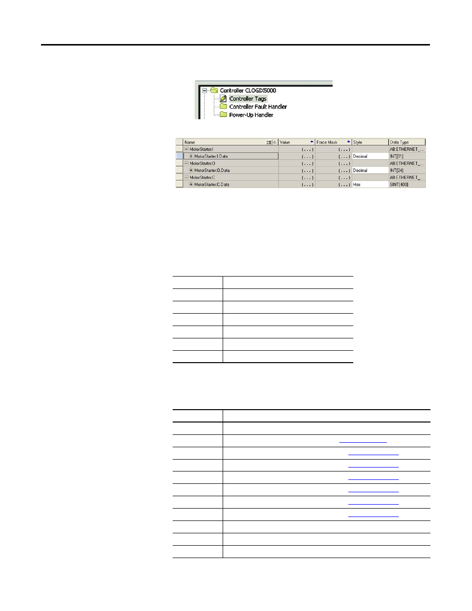
Open the Controller Tags window.
3.
Select the Monitor Tags tab.
An array of input and output tags were generated for each of the six scanned
devices. To control the output relays for the scanned device, use the output tags;
to obtain diagnostic information from the scanned device, use the input tags.
The format of output data is shown in the table to follow.
Table 6 - Output Assembly — Instance 100
The format of the input data is shown in the table to follow.
Table 7 - Input Assembly — Instance 101
Byte Size
Contents
Scan List I/O Size Data to be delivered to the first scan list entry.
Scan List I/O Size Data to be delivered to the second scan list entry.
Scan List I/O Size Data to be delivered to the third scan list entry.
Scan List I/O Size Data to be delivered to the fourth scan list entry.
Scan List I/O Size Data to be delivered to the fifthscan list entry.
Scan List I/O Size Data to be delivered to the sixth scan list entry.
Byte Size
Contents
4 bytes
Logix Status Word
2 bytes
DeviceNet Scanner Status (Parameter 1) See
2 bytes
Scan List Entry 1 Status Word (Parameter 2) See
2 bytes
Scan List Entry 2 Status Word (Parameter 3) See
2 bytes
Scan List Entry 3 Status Word (Parameter 4) See
2 bytes
Scan List Entry 4 Status Word (Parameter 5) See
2 bytes
Scan List Entry 5 Status Word (Parameter 6) See
2 bytes
Scan List Entry 6 Status Word (Parameter 7) See
Scan List I/O Size Produced I/O data from the first scan list entry.
Scan List I/O Size Produced I/O data from the second scan list entry.
Scan List I/O Size Produced I/O data from the third scan list entry.