Rockwell Automation 20-750-DNET PowerFlex DeviceNet Option Module User Manual
Page 40
40
Rockwell Automation Publication 750COM-UM002B-EN-P - October 2012
Chapter 4
Configuring the I/O
In this example, we use a 1756-DNB DeviceNet Scanner, so the 1756-
DNB option is selected.
6.
Click OK.
7.
In the Select Major Revision pop-up dialog box, select the major revision
of its firmware.
8.
Click OK.
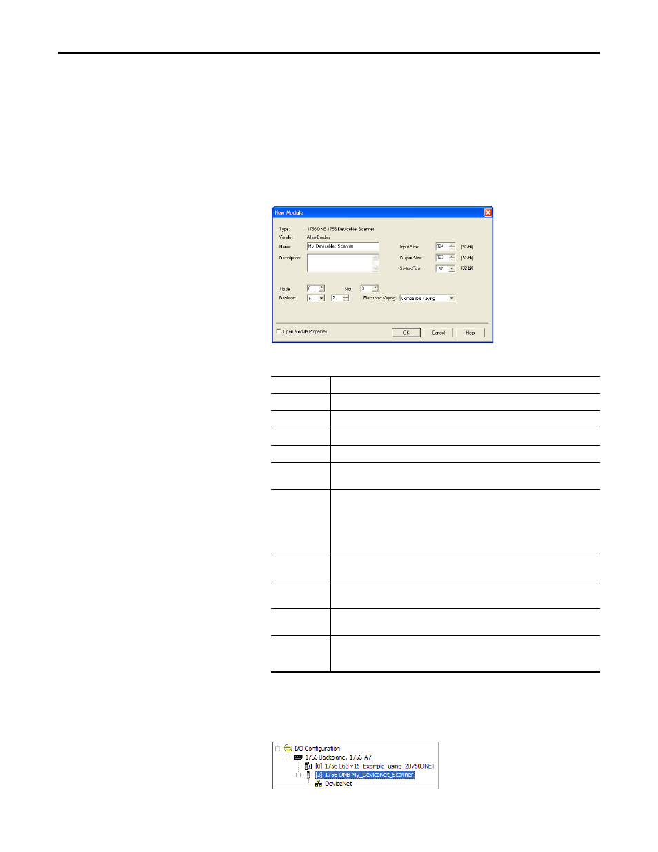
The scanner’s New Module dialog box appears.
9.
Edit the following:
10.
Click OK.
The scanner is now configured for the DeviceNet network, added to the
RSLogix 5000 project, and appears in the I/O Configuration folder.
Box
Setting
Name
A name to identify the scanner.
Description
Optional – description of the scanner.
Node
The node address of the DeviceNet scanner.
Slot
The slot of the DeviceNet scanner in the rack.
Revision
The minor revision of the firmware in the scanner. (You already set the major revision by
selecting the scanner series in step 7.)
Electronic
Keying
Compatible Keying. The ‘Compatible Keying’ setting for Electronic Keying verifies that
the physical module is consistent with the software configuration before the controller
and scanner make a connection. Therefore, be sure that you have set the correct revision
in this dialog box. See the online Help for additional information on this and other
Electronic Keying settings. If keying is not required, select ‘Disable Keying’. Disable Keying
is recommended.
Input Size
The size of the input data for the DeviceNet scanner. We recommend using the default
value of 124.
Output Size
The size of the output data for the DeviceNet scanner. We recommend using the default
value of 123.
Status Size
The size of the status data for the DeviceNet scanner. We recommend using the default
value of 32.
Open Module
Properties
When this box is checked, clicking OK opens additional module properties dialog boxes to
further configure the scanner. When unchecked, clicking OK closes the scanner’s New
Module dialog box. For this example, uncheck this box.