Rockwell Automation 20-750-DNET PowerFlex DeviceNet Option Module User Manual
Page 30
30
Rockwell Automation Publication 750COM-UM002B-EN-P - October 2012
Chapter 3
Configuring the Option Module
configured in both the option module and the scanner. You need to set the I/O
configuration and COS parameters in the option module.
Set Up the COS (Change of State) Data Exchange (Optional)
Set
Device Parameter 11 - [COS Status Mask] for the bits in the Logic Status
word that should be checked for changes. For the Logic Status bit definitions, see
or the drive documentation.
1.
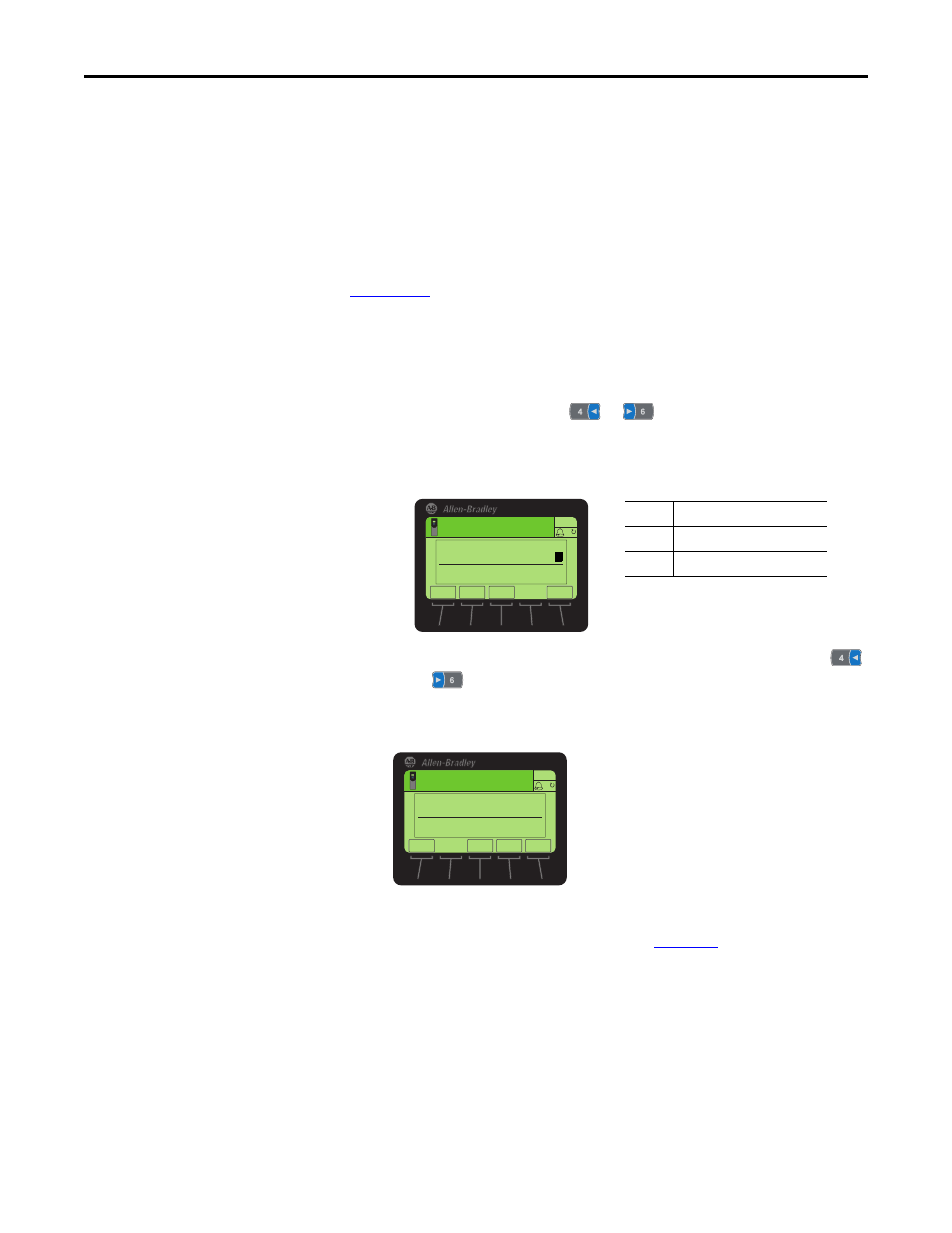
Edit any of the bits as required.
a. Press the EDIT
soft key to display the Edit COS Status Mask screen.
b. To toggle a bit between 0 or 1, press any numeric key—except the
or
key.
2.
Set
Device Parameter 12 - [COS Fdbk Change] for the amount of change
to the Feedback that is required to trigger a Change of State message.
The option module is now configured for COS data exchange. You must
configure the scanner to allocate it using COS (
TIP
The 20-HIM-A6 or 20-HIM-C6S HIM shows 32-bit Bit-type parameters in two
16-bit sets. By default, the lower 16-bit set (bits 0…15) is shown. To view the
upper 16-bit set (bits 16…31), press the UPPER soft key. To view the lower 16-
bit set again, press the LOWER soft key. To select each bit position, use the
or soft key or the
or
numeric key.
Value
Description
0
Ignore this logic bit. (Default)
1
Use this logic bit.
ESC
ENTER
Stopped
0.00 Hz
AUTO
F
Edit COS Status Mask
xxxx xxxx xxxx xxx
x
ESC
ENTER
Stopped
0.00 Hz
AUTO
F
Edit COS Fdbk Change
0.000
0.000 << 3.40282E38
EXP