Connecting the option module to the network – Rockwell Automation 20-750-DNET PowerFlex DeviceNet Option Module User Manual
Page 20
20
Rockwell Automation Publication 750COM-UM002B-EN-P - October 2012
Chapter 2
Installing the Option Module
Connecting the Option
Module to the Network
1.
Remove power from the drive.
2.
Remove the drive cover and lift up the drive HIM bezel to its open
position to access the drive control pod.
3.
Use static control precautions.
4.
Connect one end of the DeviceNet cable to the network. We recommend
DeviceNet Thin cable with an outside diameter of 6.9 mm (0.27 in.).
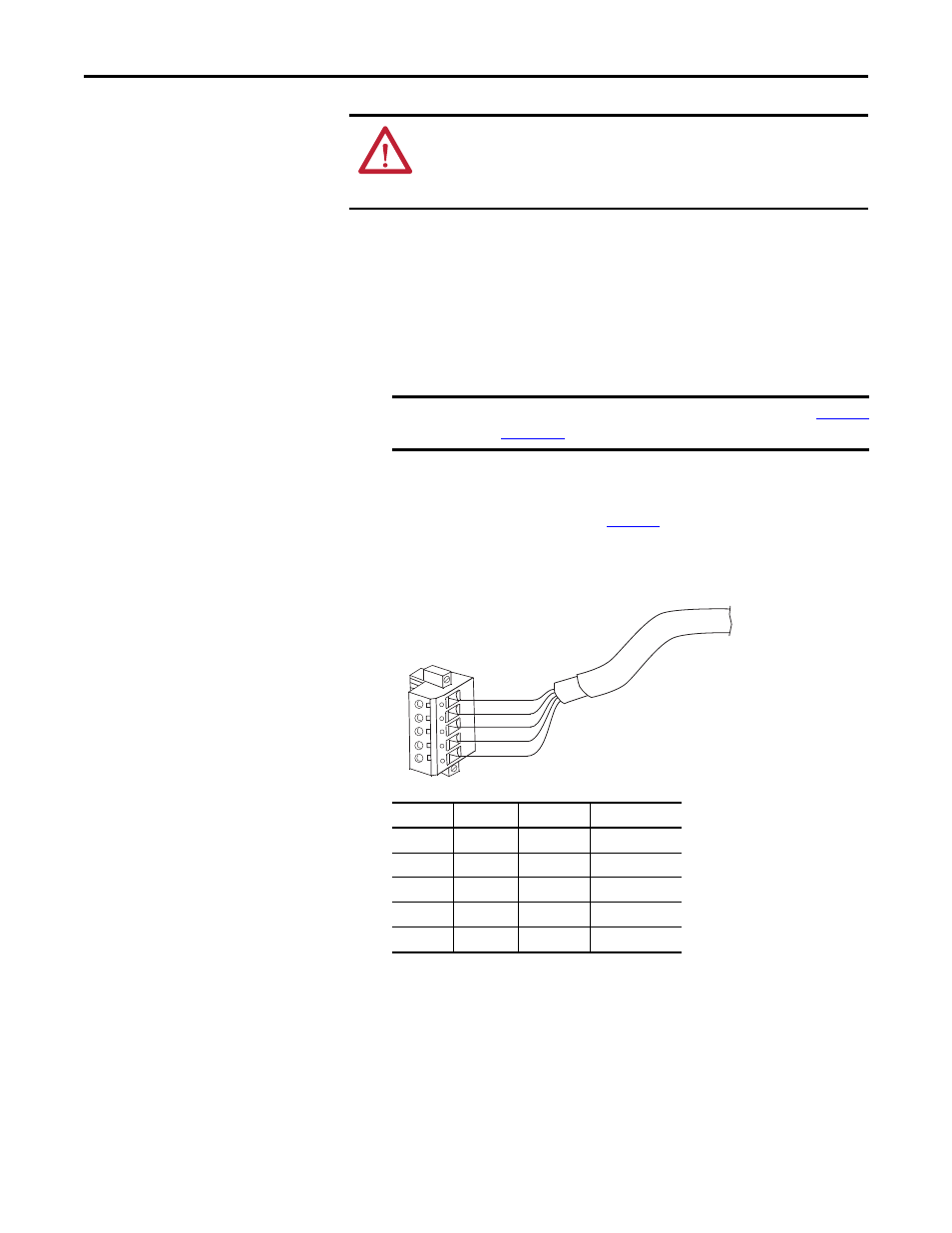
5.
Route the other end of the DeviceNet cable through the bottom of the
drive, and connect the 5-pin linear plug (provided with the option
module) to the DeviceNet cable (
Figure 3
). If a replacement plug is
needed, the replacement plug part number is 1799-DNETSCON.
Figure 3 - Connecting the 5-Pin Linear Plug to the DeviceNet Cable
6.
Insert the 5-pin linear plug into the mating option module receptacle, and
secure it with the two screws. Verify that the colors of the wires on the plug
match the color codes on the receptacle.
ATTENTION: Risk of injury or death exists. The PowerFlex drive may contain high
voltages that can cause injury or death. Remove power from the drive, and then
verify power has been discharged before connecting the option module to the
network.
IMPORTANT
Maximum cable length depends on data rate. For details, see
.
Terminal
Color
Signal
Function
5
Red
V+
Power Supply
4
White
CAN_H
Signal High
3
Bare
SHIELD
Shield
2
Blue
CAN_L
Signal Low
1
Black
V–
Common
5
4
3
2
1
Red
White
Bare
Blue
Black