Blade ICE RACKSWITCH G8124-E User Manual
Page 91
BLADEOS 6.5.2 Application Guide
BMD00220, October 2010
Chapter 6: VLANs 91
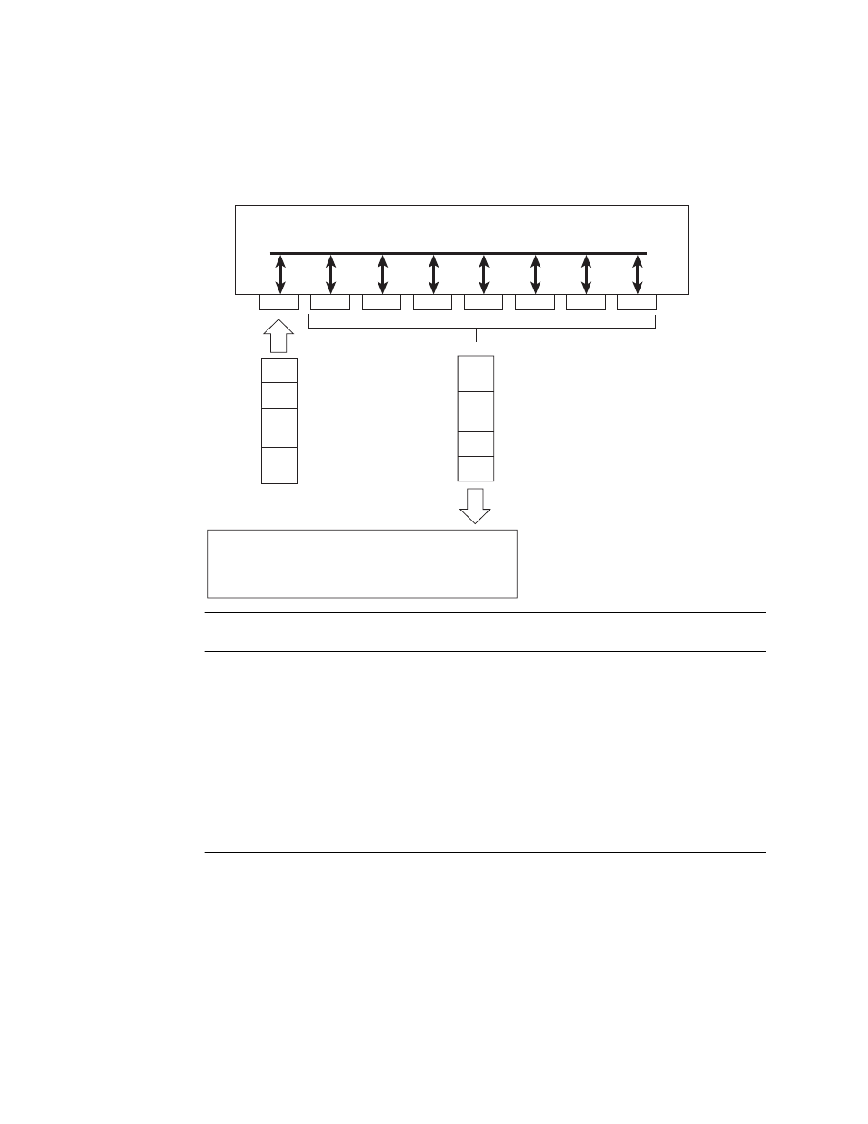
Figure 1
Default VLAN settings
Note –
The port numbers specified in these illustrations may not directly correspond to the physical
port configuration of your switch model.
When a VLAN is configured, ports are added as members of the VLAN, and the ports are defined as
either tagged or untagged (see
through
).
The default configuration settings for the G8124 has all ports set as untagged members of VLAN 1
with all ports configured as PVID = 1. In the default configuration example shown in
incoming packets are assigned to VLAN 1 by the default port VLAN identifier (PVID =1).
through
illustrate generic examples of VLAN tagging. In
, untagged
incoming packets are assigned directly to VLAN 2 (PVID = 2). Port 5 is configured as a tagged
member of VLAN 2, and port 7 is configured as an untagged member of VLAN 2.
Note –
The port assignments in the following figures are not meant to match the G8124.
Port 1
DA
SA
Data
CRC
Incoming
untagged
packet
BS45010A
Port 2
Port 3
Port 4
Port 5
VLAN 1
802.1Q Switch
By default:
Key
All ports are assigned PVID = 1
All ports are untagged members of VLAN 1
PVID = 1
Port 6
...
DA
SA
Data
CRC
Outgoing
untagged packet
(unchanged)
Port 7