Wiring diagram, Cls301 – Yamato Scientific CLS600 Cool Line User Manual
Page 49
46
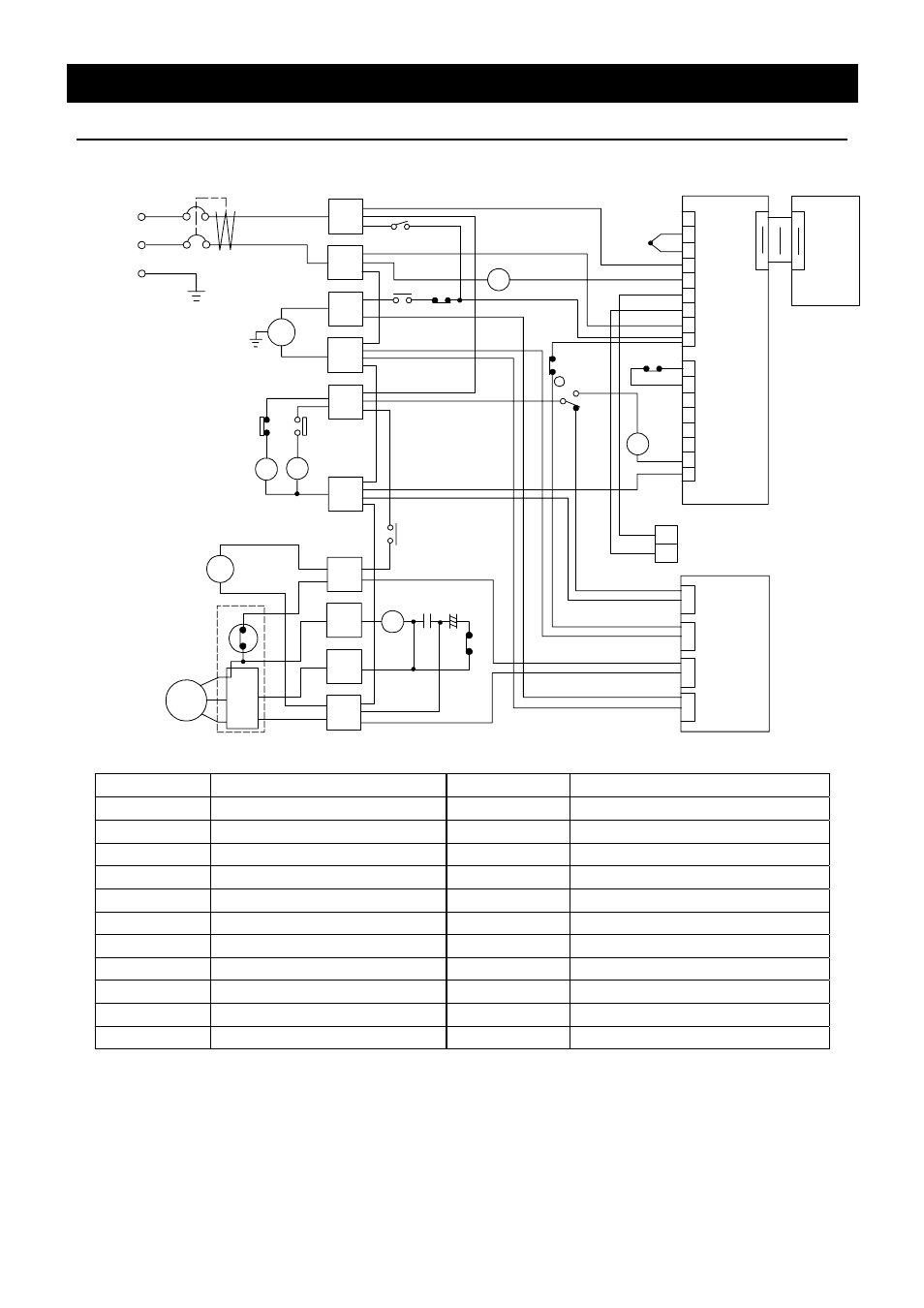
Wiring Diagram
CLS301
1
T1
ELB
2
3
5
4
AC100V
6
X1
X2
PLB
1
2
TB1
PIO
1
20
CN1
CN1
20
1
3
4
5
6
7
8
9
10
11
TB2
12
13
14
15
16
17
X3-2
X2
PSW
X3-1
PS
X3
X4-1
FS
X4
X4-2
21
+
-
FM
2
1
4
3
3
1
2
3
R
S
C
OVR
X5
C1 C2
X1
X5
RF
T2
P
T3
1
2
+
-
PV伝送出力(4-20mA)
TH
WIB
2
3
1
2
3
1
2
3
1
2
3
1
CN1
CN2
CN4
CN6
Symbol
Part name
Symbol
Part name
ELB
Earth leakage breaker C2
Start
condenser
T1
Terminal block
X5
Start relay
T2
Terminal block
WIB
Operation display board
T3
Terminal block
PSW
Power switch
PLB
PLANAR board
P
Magnet pump
PIO
Display board
X1
Relay (refrigerator)
TH
Temperature sensor (T)
X2
Relay (error)
FM
Fan motor
X3
Relay (pressure)
RF Compressor
X4 Relay
(flow)
OVR
Overload relay
PS
Pressure switch
C1
Operation condenser
FS
Flow sensor
PV transmission output
This manual is related to the following products: