Channel assignments – SATEC BFM136 User Manual
Page 44
Chapter 4 PAS Application Software
General Meter Setup
44
BFM136 Branch Feeder Monitor
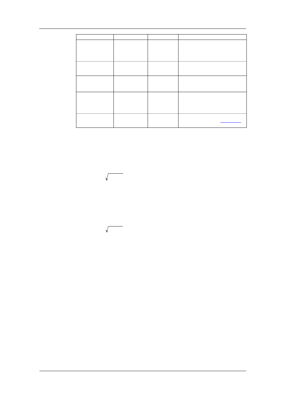
Parameter
Options
Default
Description
Energy roll value,
kWh
100000.0 kWh
1000000.0 kWh
10000000.0 kWh
100000000.0 kWh
100000000.0
The value at which energy counters
roll over to zero
Energy LED pulse
rate, Wh/pulse
0.01-100.00
5.40 Wh/pulse
(one equivalent
disk revolution)
LED pulse constant - the amount of
accumulated energy (in secondary
readings) giving one pulse via “Wh”.
Energy LED Test
Disabled,
Wh Pulses,
varh Pulses
Disabled
The type of accumulated energy
giving pulses via “Wh” LED.
Energy LED Pulse
source
SubMeter 1,
SubMeter 2,
…
SubMeter 40
SubMeter 1
The submeter uses as source of
accumulated energy giving pulses via
“Wh” LED.
Volts Scale, V
60-600 V
600 V
The maximum voltage scale allowed,
in secondary volts. See
Appendix E
Power Calculation Modes
The power calculation mode option allows you to change the method for
calculating reactive and apparent powers in presence of high harmonics. The
options work as follows:
1. When the reactive power calculation mode is selected, active and reactive
powers are measured directly and apparent power is calculated as:
2
2
Q
P
S
This mode is recommended for electrical networks with low harmonic
distortion, commonly with THD < 5% for volts, and THD < 10% for currents.
In networks with high harmonics, the following method is preferable.
2. When the non-active power calculation mode is selected, active power is
measured directly, apparent power is taken as product S = V x I, where V
and I are the RMS volts and amps, and reactive power (called non-active
power) is calculated as:
2
2
P
S
N
Channel Assignments
The Channel Assignments setup allows you to link the device current
terminals to submeters so they can monitor them. Additionally, this setup
allows you to specify the primary current rating of the current transformers
connected to the device terminals. The number of the selected current inputs
for a submeter specifies if it will be a single-, two-, or three-phase meter.
Always select your submeters (both metering and totalization) in a sequence
without gaps so that your device does not occupy unnecessary network
addresses.
To enter the setup dialog, select the device site from the list box on the PAS
toolbar, select General Setup from the Meter Setup menu, and then click on
the Channel Assignments tab.