T-armor, Ul 580 wind uplift information (cont.) – Metal Sales T-Armor Series User Manual
Page 29
© Metal Sales Manufacturing Corporation / Subject to change without notice 09/14
29
T-ARMOR
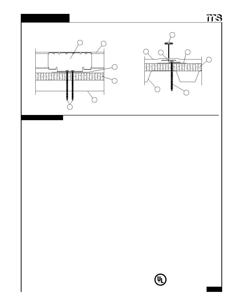
1. Metal Roof Deck Panels* - No. 24 MSG steel or stainless steel or 0.030 in. thick aluminum, nom 18 in. wide,
2-3/8 in. high standing seams. Heavier gauges or narrower panels acceptable. Panels continuous over two or
more spans. Floating end laps to occur over purlins with panels overlapped 8 in. End lap to begin 3 in. from purlin
web and to extend across purlin flange. A bead of mastic sealant may be used at panel end and side laps.
2. Panel Clips* - No. 16 MSG min gauge coated steel or stainless steel, 6 in. long by 2.718 in. high. Base to have
four .281 in. dia. guide holes to accommodate screw fasteners (Item 4). Clips spaced 48" on center maximum,
fastened throught metal decking.
3. Cap - Used at seam, nom 1 in. wide, 1/2 in. deep fabricated from min No. 24 MSG steel, stainless steel or 0.030
in. thick aluminum. Cap continuously seamed over panel seams with a special motorized seaming tool. Seaming
process to include panel clips (Item 2)
4. Fasteners - (Screws) - Fasteners used to attach panel clips (Item 2) to liner panel to be No. 12 self-tapping, hex-
head, plated or stainless steel screw without washers or #14-13 with No. 3 phillips head Deck Screw. Two fasten-
ers per clip to be used. Fasteners used to attach thermal spacer (Item 9) to purlins to be same type spaced 18 in.
OC. Fasteners used at end lap to be expanding bolt type with an aluminum sleeve having a 5/8 in. diam cap with a
1/4-20 by 1-7/16 in. long stainless steel bolt. Spacing at end lap to be 1, 3, 3, 4, 3, 3 in. pattern. Length to depend
on thickness of insulation and/or thermal spacers and to be 3/4 in. longer than overall depth of deck assembly.
5. Foamed Plastic - (Optional) - Extruded foamed plastic (rigid Insulation) min density 2.00 pcf supplied in min thick-
ness 1 in., max thickness 4 in.
6. Liner Panel - Fabricated from No. 22 MSG min thickness coated steel. Min depth 15/16 in., max pitch 7.2 in., min
yield strength 33 ksi. or 18/20 MSG thickness (No 22 MSG min) coated steel, 4-1/2 in. deep, (24 in. coverage), min
yield strength 33 ksi. Max span of panel units to be per manufacturer's instructions. Panels attached to structural
supports with screws or welds per liner panel manufacturer's instructions.
7. Bearing Plate - (Optional) - No. 22 MSG steel, 6 in. by 6 in. Used with rigid insulation only.
8. Supports (Purlins) - (Not Shown) - Purlins used for liner panels to be cold fomred steel sections. As alternates,
structural steel components (hot rolled beams, channels, open web joist etc.) may be used. Min gauge and yield
to depend on design considerations. Max spacing to depend on design considerations.
9. Thermal Spacer - (Optional) - (Not Shown) - Located over liner panel at panel clip locations. Continuous nom
wood 2 in. by 4 in. Not used when foamed plastic (Item 5) is used.
Refer to General Information, Roof Deck Construction (Roofing Materials and Systems Directory) for items not evalu-
ated.
10. Plywood or OSB - (Optional) (Not Shown) - Min APA rated plywood, nom 1/2 in. thick or oriented strand board
(OSB), nom 7/16 in. thick, 4 x 8 ft. Sheets to be installed on top of Foamed Plastic (Item 5) in lieu of bearing plates
(Item 7)
*Bearing the UL Classification Mark
Construction No. 268A
July 15, 2013
Uplift - Class 90
Fire Not Investigated
UL 580 WIND UPLIFT INFORMATION (CONT.)
T-ARMOR
2
2
1
3
3
7
7
5
5
6
6
4
4
Underwriters Laboratories Inc.
®
LISTED