6 communication interfaces, 1 usb interface – Memmert HPP 108/749 Constant climate chamber (Generation 2003) User Manual
Page 50
50
Advanced functions
Setting:
1. Set the desired humidity balance point in the SETUP (see page 42 ) and set the accompa-
nying compensation correction value to 0.0 %rh.
2. With a reference instrument, measure the deviation in the stationary state in the selected
humidity balance point.
3. Set the compensation correction value in the SETUP. If the measured reference humidity is
too low, the compensation correction value must be set with a negative sign.
4. Perform a control measurement with the reference instrument.
The procedure can be performed with humidity balance points of 20 % rh and 90 % rh.
Example: Humidity deviation at 90 % should be corrected.
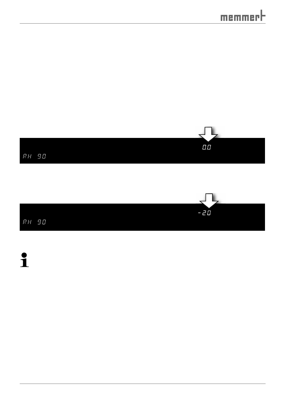
1. Set humidity balance point in the SETUP to RH 90 and set the accompanying compensation
correction value to 0.0 % rh:
SETUP
loop
t3
t4
t2
t1
on
off
Mo
Tu
We
Th
Fr
Sa
Su
3
4
2
1
STERI
DEFRO
°C
°C
rh
mb
%
CO
mb
2
IN 1
IN 2
OUT
MIN
AUTO
MAX
rh
b
%
%
%
2. With a calibrated reference instrument, an actual humidity of 88 % rh is measured at nor-
mal operation, with a set setpoint humidity of 90 % rh.
3. Set the compensation correction value in the SETUP for RH 90 to –2.0 % rh:
SETUP
loop
t3
t4
t2
t1
on
off
Mo
Tu
We
Th
Fr
Sa
Su
3
4
2
1
STERI
DEFRO
°C
°C
rh
mb
%
CO
mb
2
IN 2
OUT
IN 1
IN 2
OUT
MIN
AUTO
MAX
rh
rh
mb
%
%
%
%
%
IN 2
OUT
4. The reference instrument should display 90.0 % rh after the calibration procedure.
With RH 20, a further comparison can be programmed at 20 % relative humidity.
If all compensation correction values are set to 0.0 % rh, the factory calibration settings
are restored.
7.6
Communication interfaces
Depending on the model, the constant climate chamber can be fitted with different commu-
nication interfaces (USB, RS 232/485, Ethernet). These are located on the rear of the appliance.
7.6.1 USB interface
The chamber is fitted by default with a USB interface in accordance with the USB specification.
With this interface it is possible to control and log the chamber remotely from the computer.
For this, the “Celsius“ software is used.
The chamber must be given a unique device address in the SETUP submenu, menu item AD-
DRESS, via which the computer communicates with the oven (see page 42 ). The default setting
is ADDRess 0. Using this, the appropriate incubator can be selected and programmed from the
computer.
If several chambers are to be connected to a computer via USB interface, an appropriate inter-
face on the computer and a separate cable are required for each chamber.
The maximum cable length is 5 m.