E84aycec communication manual (ethernet powerlink) – Lenze E84AYCEC User Manual
Page 42
E84AYCEC communication manual (Ethernet POWERLINK)
Commissioning
Initial switch-on
42
L
EDS84AYCEC EN 3.0 - 09/2012
Initial switch-on and diagnosing
1. Switch on the controller and check whether it is ready for operation using the
diagnostic LEDs of the communication module.
• Red diagnostic LEDs must not be on.
• The following signalling should be visible:
2. If not already done, load the EPL configuration into the controller.
3. Repeat steps 1 and 2 for all EPL nodes.
4. Start network.
The network starts automatically if you set the managing node last.
Otherwise there are two options:
• Switch off the network nodes and switch them on together or
• execute a fault reset on the managing node (EPL address 240).
5. Check the EPL network again using the diagnostic LEDs of the communication
module.
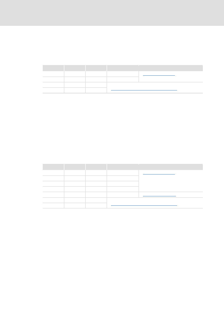
The following signalling should be visible:
LED
Colour
Status
Meaning
MS
Green
On
Module Status
DE
-
Off
Device Error
X251
Green
On
LED is lit if a connection to the node has been established.
Status displays at the RJ45 sockets (X251, X252) ( 56)
X252
Green
On
LED
Colour
Status
Meaning
MS
Green
On
Module Status
ME
-
Off
Module Error
BE
-
Off
Bus Error
DE
-
Off
Device Error
BS
Green
On
Bus Status
Fieldbus status displays ( 55)
X251
Green
On
LED is lit if a connection to the node has been established.
Status displays at the RJ45 sockets (X251, X252) ( 56)
X252
Green
On