Level planter, Level planter -8 – Kinze 3660 Lift and Rotate Planter Rev. 7/14 User Manual
Page 20
M0217-01
Model 3660
2-8
Rev. 7/11
TM
Machine Operation
6. Connect ASABE Standards 7 terminal connector for safety/warning lights on planter to ASABE Standards
receptacle on tractor. If your tractor is not equipped with an ASABE Standards receptacle, check with your tractor
manufacturer for availability. Check warning lights on planter work in conjunction with warning lights on tractor.
NOTE: A 12 volt battery connection is required to power the vacuum fan digital gauge. Connect “red” wire to
positive (+) battery terminal and “black” wire to negative (-) battery terminal.
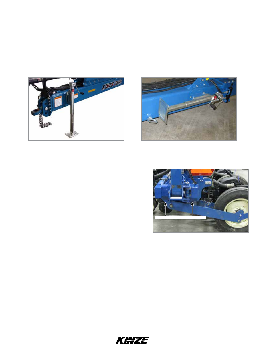
7. Raise jack stand and remount horizontally on storage bracket on opposite side of hitch.
NOTE: DO NOT install safety chain using clevis hardware. Move safety chain location if necessary.
2. Remove clevis hitch hex head cap screw and lock nut using a torque wrench. Replace if off-torque is below 75 ft-lb
(101.6 N-m) or there is corrosion or damage.
NOTE: Clevis must be free to move on hitch. DO NOT OVERTIGHTEN hardware.
3. Align clevis to hitch holes at new location and install hex head cap screw and lock nut. Tighten lock nut until
threads are fully engaged and hex head cap screw and lock nut are firmly against hitch bracket.
LEVEL PLANTER
Level 20" - 22" from ground
NOTE: On planters with push row units and no till coulters, uplift from down force springs or air springs in
pneumatic down pressure system may cause wings to rise slightly in planting position. Problem may be
compounded if static pressure is trapped in planter’s hydraulic lift system which can cause wing cylinders
to extend slightly. Operating tractor’s hydraulic system in float position or moving tractor’s hydraulic lever to
float position briefly to relieve pressure will help maintain proper toolbar height.
Lateral adjustment is maintained by tire pressure. Check tires
are inflated to specification.
Front and rear level adjustment is maintained by hitch clevis
position unless tractor drawbar is adjustable for height. Planter
frame and row unit parallel arms must be level for proper
planter and row unit operation. Bottom of toolbar should be 20"
to 22" from planting surface.
1. Lower planter to planting position and check planter is level
front to rear. Go to step 2 if hitch is too high or low.
Level planter toolbars
Jack in operating position
Jack in storage position