Rear view of front panel, Rev. 10/12 – Kinze 3660 Lift and Rotate Planter Rev. 7/14 User Manual
Page 121
TM
Model 3660
M0217-01
Rev. 10/12
5-41
Lubrication and Maintenance
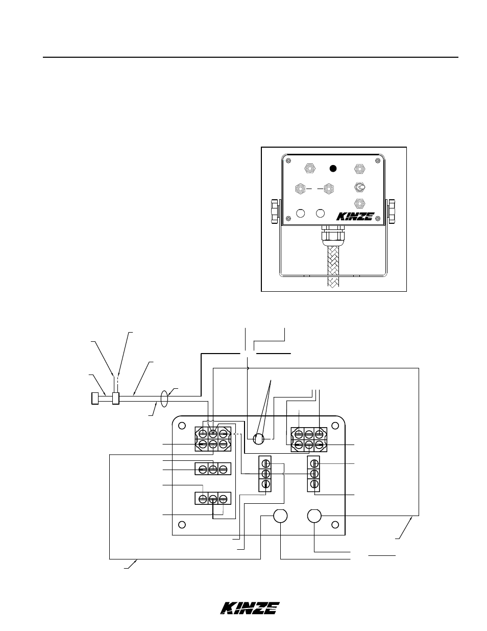
ELECTRICAL CONTROL CONSOLE SCHEMATIC
NOTE: Disconnect control console from tractor battery before doing any electrical work. Keep wiring
harnesses away from high temperature areas or sharp edges. DO NOT route wiring harnesses along battery
cables. Use cable ties to keep wire harness away from moving parts on tractor and planter. be sure tractor
frame ground connections are clean to provide good electrical contact.
FOLD
PLANT
MAIN
MARKERS
RIGHT
LEFT
OFF
RAISE
WING
LOCK
ROTATE
TONGUE
OFF
15AMP
AIR COMP.
20AMP DELAYED
DOWN PRESSURE
DECREASE
INCREASE
WORK LIGHTS
OFF
ON
OFF
FUNCTION
TM
Splice
Work Lights
Down Pressure
Plant/Fold
Raise/Wing Lock
Rotate/Tongue
+12V
From Battery
Splice
Pin W (Orange/Black)
(Purple)
(Purple/White)
Pin J (Gray)
Pin D (Blue/White)
Black
(Transformer)
Red
(Transformer)
Yellow (Backlit Panel)
Orange
(Backlit Panel)
Push Button Switch
& Transformer
Pin F (Yellow/Red)
Pin V (Blue/Black)
PIN A (Orange/Red)
Pin B (Blue/Red)
Pin O (Red)
Ground From Battery (Black)
Splice
Pin T (Black)
Pin C (Black/Red)
Rear View of Front Panel
12 Gauge Jumper
12 Gauge Jumper
Splice
Use Female Push-On Connectors
DEL.
15A
20A
Markers
3 2
1
6 5
4
3 2
1
3 2
1
3
2
1
3
2
1
3 2
1
6 5
4
Pin H (Blue)