Connecting the components – Auto Meter 6013 User Manual
Page 11
Chapter 2. Getting Started
Race Dash Users Guide
5
Labels on Long Cables
Connection To
ES
Engine speed (RPM)
OT
Oil temperature sensor
WT
Water temperature sensor
OP
Oil pressure sensor
F
Fuel pressure sensor
B +
Battery Positive
B -
Battery Negative (Ground)
Connecting the Components
1. Connect the wiring harness to the display module.
2. Connect the four switches to the cables labeled S1 to S4.
3. Connect each of the sensors that you have purchased to the
appropriate wire in the wiring harness, as shown above.
4. Connect a 12v DC power supply to the power input cable.
5. Switch on the 12v DC power supply.
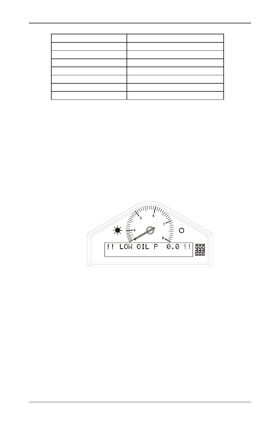
The Display Module should start up with an alarm signal
indicating low oil pressure.
This is normal in this environment.
You can now proceed to familiarize yourself with operating the
Display Module.