Auto Meter 4381 User Manual
Boost controller, Wiring installation, Installation instructions
INSTALLATION INSTRUCTIONS
2650-1706-00
®
WARNING!
The installation of the Auto Meter Boost Controller is recommended only for experienced technicians. This product may damage your engine if used properly or
improperly. Use extreme caution during installation and operation. When increasing boost, it is recommended to carefully increase the pressure in small intervals to avoid
engine damage. Auto Meter Products is not responsible for any engine damage caused by improper installation or the use of this product.
The Auto Meter Boost Controller is intended for off-road use only.
WIRING INSTALLATION
BOOST CONTROLLER
Red Wire (Power):
Connect to a switched +12 volt source.
Black Wire (Ground):
Connect to good engine ground.
White Wire (Lighting Power)
Connect to dash lighting power.
Green Wire (Optional Tach Signal)*
Connect to the negative terminal of a standard ignition coil, or to the "Tach Output" terminal on the electronic ignition module. (See Tach
Signal section for further details)
Violet Wire (Optional Speed Signal)**
Connect to vehicle speed signal. (See Speed Signal section for further details)
Blue Wire (Optional Data Logger Signal Output)***
Connect to signal input(+) or Engine Management System or Data Acquisition unit.
Black/White Wire (Optional*** Data Logger Signal Ground)***
Connect to signal input(-) on Engine Management system or Data Acquisition Unit.
Orange (Optional Pro Control Output)****
Ground trigger for auxiliary device. Maximum 2 amps at 12 volts. (See Pro Control section for further details)
Black/White Wire (Optional Pro Control Ground)****
Connect to a good ground only when Pro Control is used. Pro Control ground reference point. (See Pro Control section for further details)
Gray Wire (Optional Pro Control Ground)****
Grounding this will shut down the Boost Control Valve. This can connect the pro control output to another gauge.
* Only used if Boost by RPM or Boost by Gear is used
** Only used if Boost by Gear is used
*** Only used if vehicle is equipped with a data logger or PCM that can utilize the signal
**** Only used if Pro Control is desired to control an auxiliary electronic device
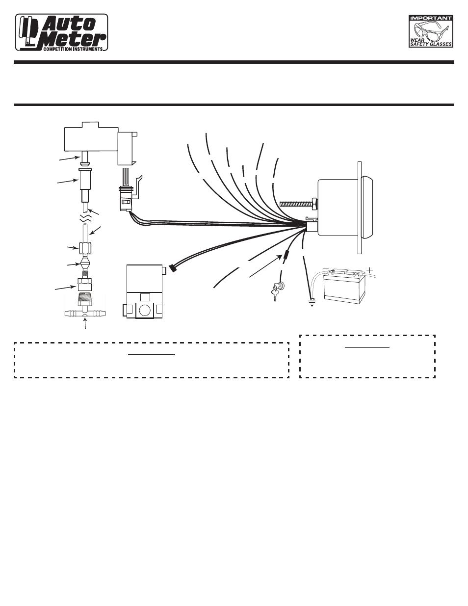
12V BATTERY
Data Logger and
Pro Control Ground
Data Logger
Output
Speed
Signal
Tach
Signal
Pro Control Input
(Optional)
Pro Control
Out
Black/White
Blue
Violet
Green
Orange
Gray
Black
White
+12v Connection
*See step 8 below
Good Engine
Ground
+12v
Dash
Lighting
Boost Control
Valve
Fuse
(see
caution
below)
Red
Compression
Adapter
Compression
Nut
Tubing Adapter
Nylon
Tubing
Pressure Port
Map Sensor (see note)
Ferrule
Vacuum “T”
3
2
1
NOTE: MAP Sensor should be mounted with
PRESSURE PORT facing down.
Failure to do so could result in
inaccurate readings due to
condensation in the line.
(Bracket fabrication may be required.)
WARNING!
Warranty will be void if connected to coil when using an aftermarket ignition box such as, but not limited to
products from the following manufacturers: MSD, Crane, Jacobs, Mallory, Holley, Etc.. Prior to installation of
your boost controller, check with the ignition box manufacturer for recommended tachometer signal location.
CAUTION!
As a safety precaution, the +12V terminal of this
product should be fused before connecting to the
12V ignition switch. We recommend using a 3 AMP
automotive type fuse.