JLG 1230ES Service Manual User Manual
Page 93
SECTION 5 - CONTROL COMPONENTS
3121222
– JLG Lift –
5-17
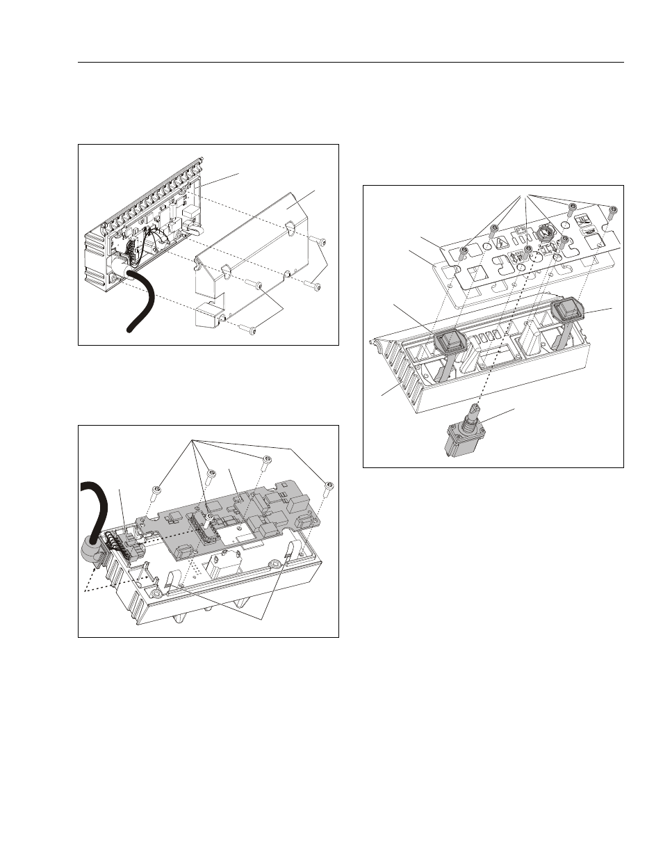
4. Loosen and remove the four (4) screws from the
upper box assembly that hold the cover to the upper
box.
1. Disconnect the upper to lower box harnness con-
nector from the printed circuit board, and unplug the
lift/drive switch blade terminals.
2. Disconnect the two (2) front button switch ribbon
cables from the circuit board.
3. Remove the five (5) screws attaching the printed cir-
cuit board to the control box.
4. Replace board and reassemble upper control box.
1. Remove the six (6) faceplate attach screws and the
lift/drive mode selector switch attach nut.
2. Carefully lift the faceplate decal and backing plate
out of the upper control box housing.
3. If replacing either of the button switches, the ribbon
cable must be disconnected from the printed circuit
board on the back, if not already done.
4. Replace component and reassemble.
Upper Control Box Cover - Installation
1. Upper Box Assembly
2. Upper Box Cover
3. Attach Screws
Upper Control Box Circuit Board - Installation
1. Circuit Board Assembly
2. Board Attach Screws
3. Upper to Lower Control Box
Harness Connector
4. Front Button Switch to Circuit
Board Ribbon Cables
1
2
3
3
1
2
3
4
Upper Control Box Faceplate Component - Installation
1. Upper Control Box Housing
2. Face Plate Attach Screws
3. Face Plate Decal
4. Face Plate - Backing Plate
5. Button Switch
6. Drive/Lift Mode Select Switch
1
2
3
4
5
5
6