Pump components, Hydraulic system pressure check port – JLG 1230ES Service Manual User Manual
Page 68
SECTION 4 - BASE COMPONENTS
4-32
– JLG Lift –
3121222
Pump Components
The following is a complete disassembly/assembly of the
machines’ pump/motor/valve assembly.
NOTE: During reassembly of the pump/motor assembly,
lubricate all seals and o-rings with JLG recom-
mended hydraulic fluid.
Also keep all internal metal parts clean and coated
with hydraulic fluid to prevent surface corrosion.
JLG recommends replacing all seals and o-rings
when disassembling and reassembling the pump/
motor unit.
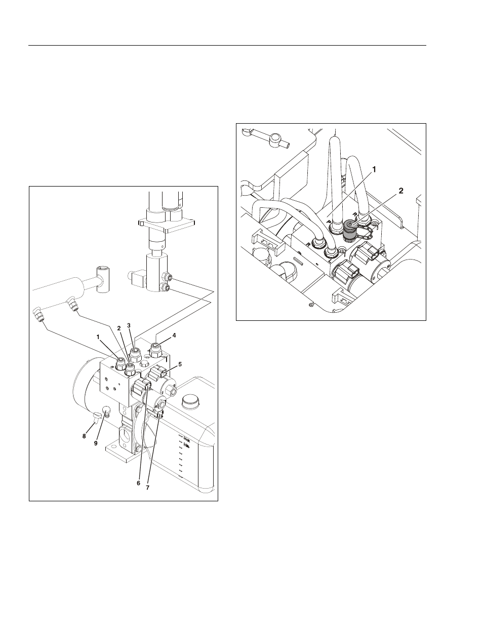
Hydraulic System Pressure Check Port
The port for hydraulic system lift pressure check is pro-
vided on the valve body of the hydraulic pump assembly
as shown in the following illustration.
Figure 4-12. Hydraulic Pump - Hydraulic Line and
Electrical Connections
1. Steer Right - Hyd. Line
2. Steer Left - Hyd. Line
3. Cyl. Lift-Up - Hyd. Line
4. Cyl. Return - Hyd. Line
5. Cylinder Lift-Up Solenoid
6. Steer Right Solenoid
7. Steer Left Solenoid
8. Pump Motor Pos (+)
9. Pump Motor Neg (–)
Hydraulic Pressure Check Port
1. Pump Valve Body
2. Pressure Check Port Shown
with Optional Fitting