4 controls & sensors, Elevation, Joystick – JLG 1230ES Service Manual User Manual
Page 33: Tilt, 5 traction, 4 controls & sensors -3, Elevation -3 joystick -3 tilt -3, 5 traction -3, 4 controls & sensors elevation
SECTION 3 - THEORY OF OPERATION - 1230ES
3121222
– JLG Lift –
3-3
3.4 CONTROLS & SENSORS
Elevation
The elevation sensor is an inductive proximity switch. It
must be powered to operate. There is a 1.3k Ohm resistor
where it connects to the ground module to produce the
proper signal for the ground module. (See electrical sche-
matic in Section 9 for details.) If Ferrous material is pres-
ent, i.e. the mast is fully retracted, it will close. The sensor
is calibrated mechanically.
The control system uses a combination of the elevation
proximity switch and pothole protection switches to deter-
mine if the platform is elevated. If these sensors do not
agree a fault is thrown.
Joystick
The joystick is used to "command" both lift and drive. The
Lift/Drive switch selects which one is applicable. This
command may be modified by the control system based
on interlocks and personalities.
On the joystick there are three switches and the control
handle. The joystick control handle sensor is not a simple
potentiometer. There is a position sensing element, and
signal conditioning circuitry in it to generate the position
signal. It is powered by 5VDC supplied from the platform
controller. When centered it will output approximately
2.5VDC. Fully forward, it will output approximately 1 VDC.
Fully backward, it will output approximately 4 VDC. On the
handle is the trigger switch that must be depressed in
order to operate the vehicle. This prevents unintentional
movement. To pass start-up tests the three switches must
be open and the joystick must be centered.
Joystick personalities to define the centered position
(where command is 0%), minimum and maximum for-
ward, as well as minimum and maximum reverse can be
accessed. Joystick system Personality settings can be
changed via ANALYZER -> PERSONALITIES -> ACCEL-
ERATOR as follows:
• FWD MIN - The forward extent of the centered position.
Values between this and REV MIN are where 0% is
commanded.
• REV MIN - The reverse extent of the centered position.
Values between this and FWD MIN are where 0% is
commanded.
• FWD MAX - Joystick voltage where 100% will be com-
manded.
• REV MAX - Joystick signal voltage where -100% will be
commanded.
Tilt
The control system monitors the tilt sensor to determine if
the vehicle is tilted excessively. This condition is called
"Tilted". In the CE, Australia and Japan markets, if the vehi-
cle tilt angle in any direction is greater than or equal to
3.5°, the control system considers the machine tilted. In
other markets, the vehicle is considered Tilted if the vehi-
cle tilt angle front to back is greater than or equal to 3.0°
or tilt left to right is greater than or equal to 1.5°.
3.5 TRACTION
The traction, or drive system, moves the vehicle along the
ground by electric motors. The Armatures (rotating wind-
ings) of the separately-excited drive motors are wired in
parallel to the Power Module's M1 and M2 terminals. The
M1 Terminal is always at the same voltage as the +B (Bat-
tery Voltage when the Line Contactor is closed) and
allows the module to measure current with the internal
shunt (extremely low impedance). The M2 Terminal is
pulled to Ground by the Armature Switch MOSFET's (con-
nected to -B Terminal).
To provide variable speed control, the Armature MOSFET
transistors switch On and Off at high frequencies (PWM/
pulse-width modulation; 16kHz). The Duty Cycle (On & Off
time) is varied to control the voltage applied to the Arma-
tures. When the MOSFET's spend 50% of the period On
and 50% Off, approximately ½ of the available power will
be applied to the Armatures (50% Duty Cycle). Similarly,
the MOSFET are On continuously (100% Duty Cycle) to
apply all available Battery power to the Armatures (as in
Driving at Full Speed).
Instead of permanent magnets, the separately-excited
drive motors use electro-magnets (called Field Windings)
located in the stator (non-rotating) portion of the motor.
Field windings are preferable to permanent magnets
because the Power Module can adjust the stator's magne-
tism for optimum motor performance. When climbing a
grade at low speeds, the Power Module may apply as
much as 40A to the field windings for more electro-motive
force. On level terrain, the Power Module will apply as little
as 14A to the fields for higher rotational speeds and better
electrical efficiency.
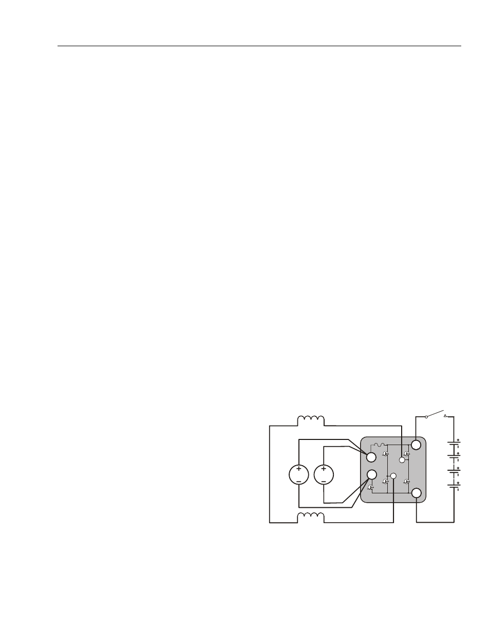
Figure 3-2. Drive Motors Schematic - 1600346 (SEV-
CON) Power Module
Line Contactor
24V
+B
–B
F2
F1
M2
M1
Power Module
Left Field Winding
Right Field Winding
Armature
Switch
Field
Switches
Shunt
1
3
2
4
Left
Armature
Right
Armature