Section 7. jlg control system, 1 electronic control system, To connect the hand held analyzer – JLG 1230ES Service Manual User Manual
Page 119: Using the analyzer, Section 7 - jlg control system, 1 electronic control system -1
SECTION 7 - JLG CONTROL SYSTEM
3121222
– JLG Lift –
7-1
SECTION 7. JLG CONTROL SYSTEM
7.1 ELECTRONIC CONTROL SYSTEM
To Connect the Hand Held Analyzer:
1. Connect the four pin end of the cable supplied with
the analyzer, to the four position connector on the
PCB and connect the remaining end of the cable to
the analyzer.
NOTE: The cable has a four pin connector at each end of
the cable; the cable cannot be connected back-
wards.
2. Power up the Control System by turning the lower
key to the platform position and pulling both emer-
gency stop buttons on.
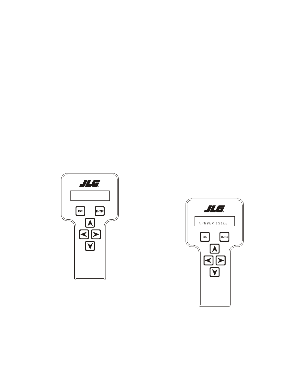
Using the Analyzer:
With the machine power on and the analyzer connected
properly, the analyzer will display the following:
HELP:
PRESS ENTER
At this point, using the RIGHT and LEFT arrow keys, you
can move between the top level menu items. To select a
displayed menu item, press ENTER. To cancel a selected
menu item, press ESC; then you will be able to scroll
using the right and left arrow keys to select a different
menu item.
The top level menus are as follows:
(Also see menu flow charts - Figure 7-1. and Figure 7-2.)
HELP
DIAGNOSTICS
ACCESS LEVEL
PERSONALITIES (See Table 7-3 on Page 7-11)
MACHINE SETUP (See Table 7-1 on Page 7-9)
ACTIVATE TESTS
CALIBRATION
If you press ENTER, at the HELP:PRESS ENTER display,
and a fault is present during power up, the analyzer dis-
play will scroll the fault across the screen. If there was no
fault detected during power up, the display will read:
In platform mode,
HELP: (001)
EVERYTHING OK,
In ground mode,
HELP: (002)
GROUND MODE OK
If ENTER is pressed again, the display moves to the fol-
lowing display:
LOGGED HELP
LOG: (211)
1: Power Cycle (Or last recorded fault)
At this point, the analyzer will display the current fault, if
MENU:
HELP:PRESS ENTER
l og: ( 211)