Hydraulic cylinder assembly testing, Hydraulic cylinder assembly testing -17, Cyl. #2/3 to cylinder joint assembly -17 – JLG 1230ES Service Manual User Manual
Page 118
SECTION 6 - MAST COMPONENTS
6-18
– JLG Lift –
3121222
Cylinder #2 and #3 Assembly to Cylinder #1
1. Replace the o-rings in the cylinder joint and rod
attach cap. Lubricate the o-rings with hydraulic oil,
however keep any oil off of the threads in the rod
attach cap.
NOTE: The attach cap threads need to be clean and free of
oil when assembled to the cylinder rod, so the loctite
applied to the cylinder rod threads will set properly.
2. Lay cylinder #1 assembly and cylinder #2/3 assem-
bly on the workbench in their approximate assem-
bled position.
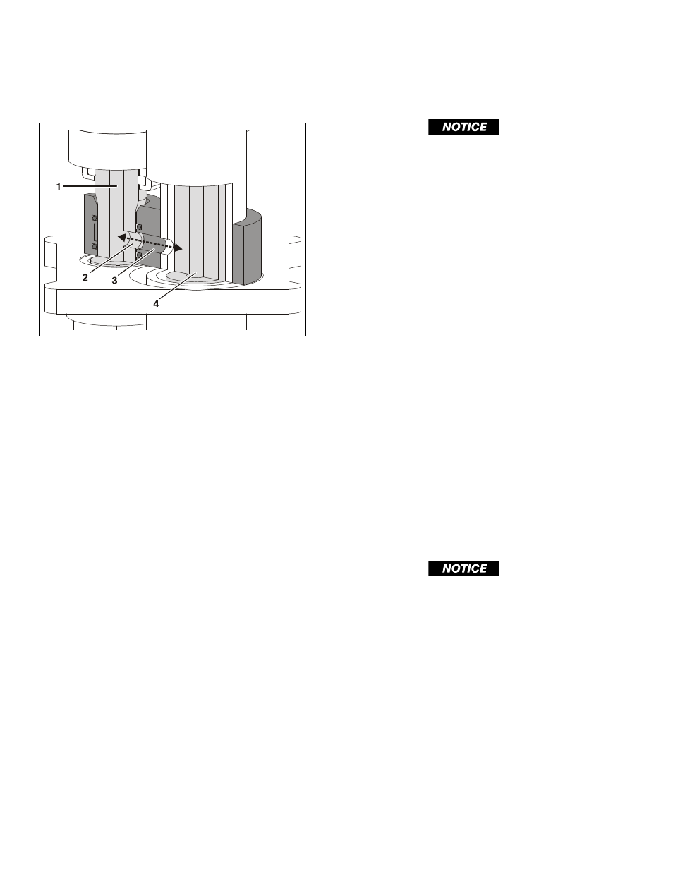
3. At the bottom end of the cylinder #2/3 assembly,
locate the hole on the side of the tapered cylinder
rod end on cylinder #2. This hole should be closely
aligned with the hole passage inside the cylinder
joint of cylinder #1 assembly when assembled.
(See Figure 6-21.)
4. Just before final assembly apply Loctite #242 to the
threads on the tapered end of the cylinder rod of the
cylinder #2/3 assembly. Slide the cylinder #2/3
assembly tapered cylinder rod end into the cylinder
joint attached to cylinder #1 aligning the hole in the
tapered cylinder rod end to the hole in the cylinder
joint.
5. Install the rod attach cap to the tapered end of the
cylinder rod and torque the cap to 200 Nm (45 ft.
lb.).
Valve Body Installation
PROTECT THE CYLINDER ROD SURFACE. DAMAGE TO THE CYL-
INDER ROD CHROME FINISH DUE TO SCRATCHING, INDENTA-
TION, CHIPPING OR OTHERWISE WILL CAUSE EVENTUAL
G L A N D S E A L F A I L U R E . T H E C Y L I N D E R R O D M U S T B E
REPLACED IF DAMAGED.
1. Lubricate and place a new o-ring in the groove on
the tapered end of cylinder rod #1.
NOTE: The cylinder rod and valve body threads need to be
clean and free of oil when the valve body is assem-
bled to the cylinder assembly, so the loctite applied
to the cylinder rod threads will set properly.
2. Clean the threads of the tapered end of the cylinder
rod of cylinder #1 and apply Loctite #242 to the
threads.
3. Apply a light film of hydraulic oil to the rod surface
above the threaded area to lubricate the o-ring when
installing the valve body to the cylinder rod end.
4. Be certain the threads inside the valve body are
clean and dry of any debris or oil.
5. Using the proper fixture to keep the cylinder rod
from turning and protect the cylinder rod from dam-
age, insert the valve body onto the end of the cylin-
der rod and tighten, then torque to 200 Nm (45 ft.
lb.).
Hydraulic Cylinder Assembly Testing
If a hydraulic cylinder testing fixture is not available to fully
pressurize the cylinder, then the cylinder must be checked
for proper operation and leaks after installation of the mast
assembly to the machine.
IF A TEST FIXTURE IS USED TO TEST THE HYDRAULIC CYLIN-
DER, DO NOT EXCEED THE MAXIMUM RATED PRESSURE SET-
T I N G O F T H E H Y D R A U L I C S Y S T E M . ( S E E S E C T I O N - 1
SPECIFICATIONS FOR MAXIMUM HYDRAULIC SYSTEM PRES-
SURE SETTINGS.)
Figure 6-21. Cyl. #2/3 to Cylinder Joint Assembly
1. Cyl. #2 - Cylinder Rod
2. Cyl. #2 - Hole in Rod
3. Passage Hole in Joint
4. Cyl. #1 - Cylinder Rod