Power module electrical evaluation, Power module electrical evaluation -8, Sevcon power module terminals -8 – JLG 1230ES Service Manual User Manual
Page 84
SECTION 5 - CONTROL COMPONENTS
5-8
– JLG Lift –
3121222
DO NOT OVERTIGHTEN THE TERMINAL BOLTS, OR DAMAGE TO
THE UNIT COULD OCCUR.
3. Torque the terminal bolts to 5 ft lb. (7 Nm).
4. After all connections to the power module are made,
the battery can be reconnected.
Power Module Electrical Evaluation
Several basic electrical tests can be performed on the
Power Module. Failure of one of these evaluations is sig-
nificant and may indicate that the device is physically
damaged. If a Power Module is suspected to be faulty,
thoroughly examine the rest of the system for possible
damage.
Make all measurements with a voltmeter set to resistance
scale (Ohms) (Refer to Section 9 - Figure 9-2., Resistance
Measurement). Disconnect the Main Battery Disconnect
and all cables from the Power Module during this analysis.
Wait 60 seconds after power is disconnected to allow
internal charge to dissipate (risk of hazard, improper read-
ings otherwise).
1. RESISTANCE >100K OHMS ALL TERMINALS TO
HOUSING.
Ensure that there is an open-circuit between all ter-
minals of the Power Module and the module's alumi-
num housing. The device is fully potted and all
electronics are insulted from the housing. Place the
Black meter lead on the housing and use the Red
meter lead to probe all terminals.
2. RESISTANCE < 2 OHMS BETWEEN +B AND M1.
Ensure that there is a short-circuit between the +B
and M1 Terminals. Internally, there is a low-imped-
ance current measurement shunt for the Armature
portion of Traction. Place the Red meter lead on +B,
and the Black meter lead on M1.
3. RESISTANCE >1M OHMS BETWEEN F1 AND -B;
F2 AND -B.
Ensure that there is an open-circuit between the two
Field Terminals (F1 & F2) and -B. Internally, there are
MOSFET transistors between these terminals that
should be high-impedance when the module is un-
powered. Place the Black meter lead on -B and the
Red meter lead on F1 / F1.
4. RESISTANCE >1M OHMS BETWEEN F1 AND
+B; F2 AND +B.
Ensure that there is an open-circuit between the two
Field Terminals (F1 & F2) and +B. Internally, there
are MOSFET transistors between these terminals
that should be high-impedance when the module is
un-powered. Place the Black meter lead on +B and
the Red meter lead on F1 / F1.
5. RESISTANCE >100K OHMS BETWEEN P AND -B.
Ensure that there is an open-circuit between the P
and the -B Terminals. Internally, there are MOSFET
transistors between these terminals that should be
high-impedance when the module is un-powered.
Place the Black meter lead on -B, and the Red meter
lead on P. Note that a measurement of increasing
resistance (capacitor charge) is normal, but a persis-
tently low impedance is not.
6. RESISTANCE >1K OHMS BETWEEN M2 AND -B.
Ensure that there is an open-circuit between the M2
and -B Terminals. Internally, there are MOSFET tran-
sistors between these terminals that should be high-
impedance when the module is unpowered. Place
the Black meter lead on -B, and the Red meter lead
on M2. Note that a measurement of increasing resis-
tance (capacitor charge) is normal, but a persistently
low impedance is not.
7. RESISTANCE 120 OHMS BETWEEN PINS 10 &
11.
Ensure that the resistor that terminates the CANbus
is within tolerance between pins 10 and 11 on the 12
position Mini-Fit Jr (Connector "B"). Place the Red
meter lead on pin 10, and the Black meter lead on
pin 11. The resistance should measure between 110
- 130 Ohms.
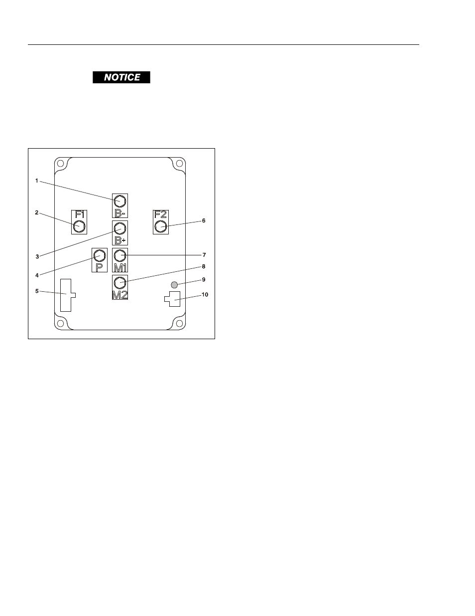
Figure 5-4. Sevcon Power Module Terminals
1. B – (battery (–) terminal)
2. F1 (motor field terminal)
3. B+ (battery (+) terminal)
4. P - (pump (–) terminal)
5. Mini-Fit Jr/B-Connector
6. F2 - (motor field terminal)
7. M1 - (motor armature terminal)
8. M2 - (motor armature terminal)
9. DTC Flash Code LED Indicator
10. Unused