Pump/motor/valve assembly - removal/installation – JLG 1230ES Service Manual User Manual
Page 70
SECTION 4 - BASE COMPONENTS
4-34
– JLG Lift –
3121222
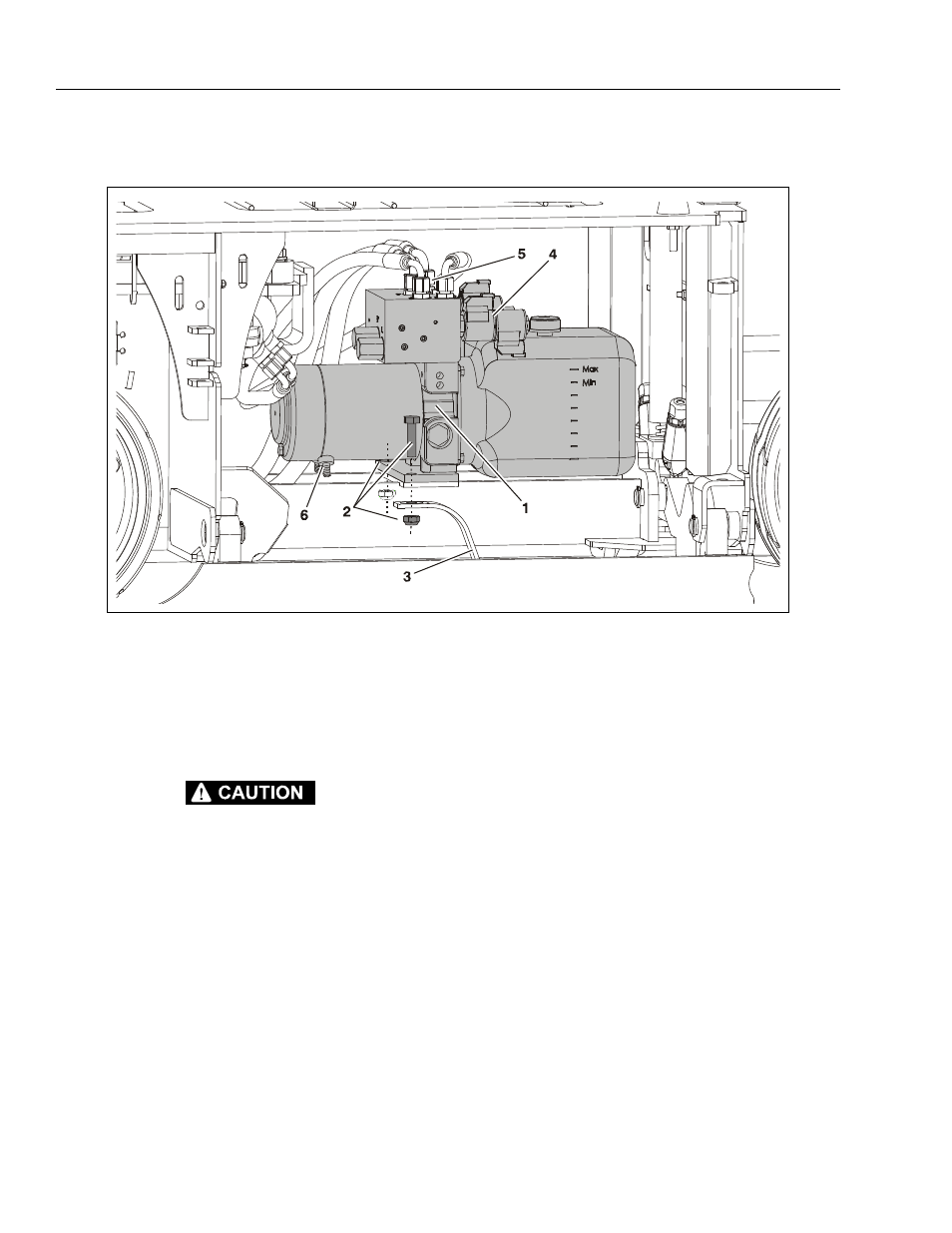
Pump/Motor/Valve Assembly - Removal/Installation
BE CERTAIN THE MAST IS FULLY LOWERED BEFORE REMOV-
ING ANY HYDRAULIC LINES FROM THE PUMP UNIT. WEAR PRO-
TECTIVE GEAR WHEN WORKING AROUND PRESSURIZED
HYDRAULIC LINES. REMOVE CONNECTIONS CAREFULLY AND
CAP ALL LINES.
1. Disconnect machine electrical power using the
quick disconnect on the left side batteries.
2. Disconnect the pump motor power cables from the
power terminals on the side of the motor housing.
3. Label and then unplug the harness connectors from
the lift-up, and steer solenoids on the pump valve
bank assembly.
4. Label and carefully disconnect the hydraulic lines
from the top of the valve bank assembly.
5. Finally remove the two (2) mounting screws and
nuts from pump mounting plate under the pump and
remove the pump/motor/valve assembly from the
machine.
Hydraulic Pump/Valve/Tank - Installation
1. Pump/Valve/Tank Assembly
2. Pump Assy. Mounting Screw/Nuts
3. Static Strap
4. Valve Bank Solenoid Connections
5. Steer/Lift-Up/Return Hydraulic Lines
6. Pump Motor Power Connection Terminals (a)
NOTE: (a) Apply dielectric grease to terminals during installation of cables. Torque nuts to 5 - 7 ft. lb. (7 - 9 Nm)