7 accessory, 7 electric motor, 7 accessory -16 7-7 electric motor -16 – JLG 1230ES Service Manual User Manual
Page 148: 6 communication
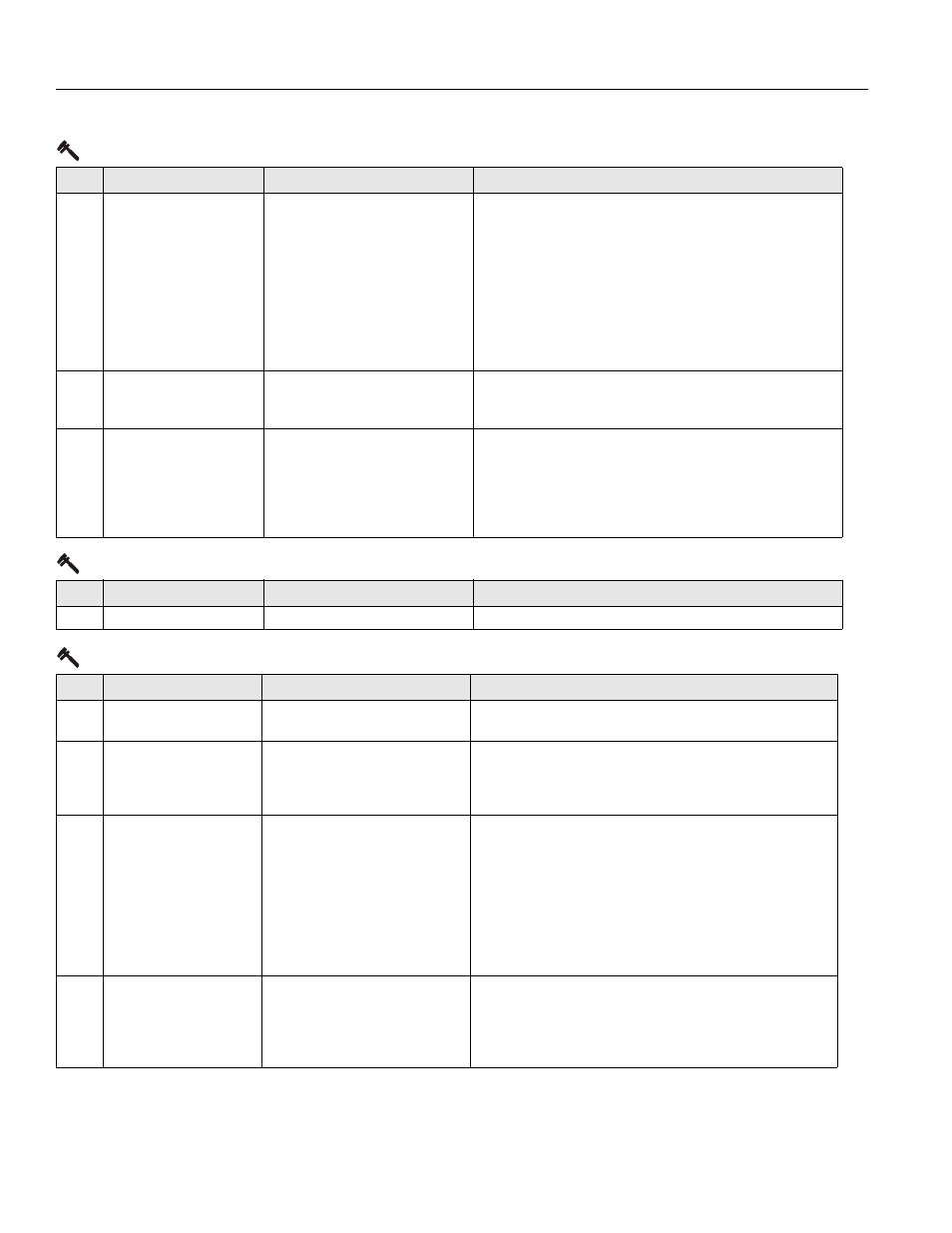
SECTION 8 - DIAGNOSTIC TROUBLE CODES
8-16
– JLG Lift –
3121222
663
CANBUS FAILURE - LOAD
SENSING SYSTEM MODULE
With load sensing system enabled, the
control system failed to receive mes-
sages from the load sensing system mod-
ule.
• Check ANALYZER -> MACHINE SETUP -> MODEL NUMBER is
correct.
• Check ANALYZER -> MACHINE SETUP -> MARKET is correct.
• Check ANALYZER -> MACHINE SETUP -> LOAD is correct.
• Check for 24V between load sense system module connector J1-
1 and J1-2.
• Turn on machine in platform mode. If DTC 662 is present, trouble-
shoot that DTC before continuing.
• Refer to Section 2.3: Troubleshooting in the LSS manual,
3124288.
664
CANBUS FAILURE - ACCES-
SORY MODULE
An accessory module has stopped com-
munication.
• Turn on machine in platform mode. If DTC 662 is present, trouble-
shoot that DTC before continuing.
• See accessory module documentation for troubleshooting.
6635 CANBUS FAILURE - CHASSIS
TILT SENSOR
Chassis Tilt Sensor messages not
received for 1000 mS while B+ is pres-
ent on J1-28
• The control system failed to receive messages from the Chassis
Tilt Sensor located inside the Ground Control Box.
• Ensure that +B is present on pin 1 of the sensor, and -B is pres-
ent on pin 4. Check the CANbus wiring to pins 2 and 3 of the sen-
sor.
• ZAPI - HEALTH (Status LED) - ON
6-7 Accessory
DTC
FAULT MESSAGE
DESCRIPTION
CHECK
671
ACCESSORY FAULT
An accessory module is reporting a fault.
• See accessory module documentation for troubleshooting.
7-7 Electric Motor
DTC
FAULT MESSAGE
DESCRIPTION
CHECK
771
OPEN CIRCUIT DRIVE
MOTOR WIRING
The power module detected a problem in
the drive motors' power circuit wiring.
• Refer to Drive Motor Electrical Evaluation in Section 3.5.
• Refer to Power Module Electrical Evaluation in Section 3.6.
772 STALLED TRACTION MOTOR
OR POWER WIRING ERROR
Drive, Steer, and Lift Prevented
• The System Module detected armature current feedback > 4.5V
or < 0.5V. This is mostly likely caused by a stalled traction motor
or power wiring issue. Alternately, it could be an internal fault.
• ZAPI - HEALTH (Status LED) - ON
773 CAPACITOR BANK FAULT -
CHECK POWER CIRCUITS
Drive, Steer, and Lift Prevented
• There is an internal or external fault that prevents the System
Module’s capacitor bank from charging.
• The System Module detected that the VMN of the pump and trac-
tion has not increased more than 1.3V in 1000mS. Alternately,
the VMN of the pump or traction is less than 20% of battery volt-
age.
• If this message persists after disconnecting the drive and pump
wiring, there is an internal fault.
• ZAPI - HEALTH (Status LED) - ON
774 SHORT CIRCUIT FIELD WIR-
ING
Drive, Steer, and Lift Prevented
• The field wiring passed System Module power-up diagnostics.
However, an external short circuit was detected when current
was applied to F1 / F2. This situation is caused by improper field
wiring or a damaged motor.
• ZAPI - HEALTH (Status LED) - ON
6-6 Communication
DTC
FAULT MESSAGE
DESCRIPTION
CHECK