Hydraulic cylinder - disassembly, Hydaulic cylinder - disassembly -14, Valve block - removal -14 – JLG 1230ES Service Manual User Manual
Page 115: Cylinder #2 and #3 assembly - removal -14
SECTION 6 - MAST COMPONENTS
3121222
– JLG Lift –
6-15
Hydraulic Cylinder - Disassembly
The following disassembly procedures shows the com-
plete disassembly sequence of the cylinder assembly.
However, your situation may not require complete disas-
sembly, choose which procedures are required to repair
the cylinder assembly for your situation.
DISASSEMBLY OF THE CYLINDER SHOULD BE PERFORMED ON
A CLEAN WORK SURFACE IN A DIRT FREE WORK AREA.
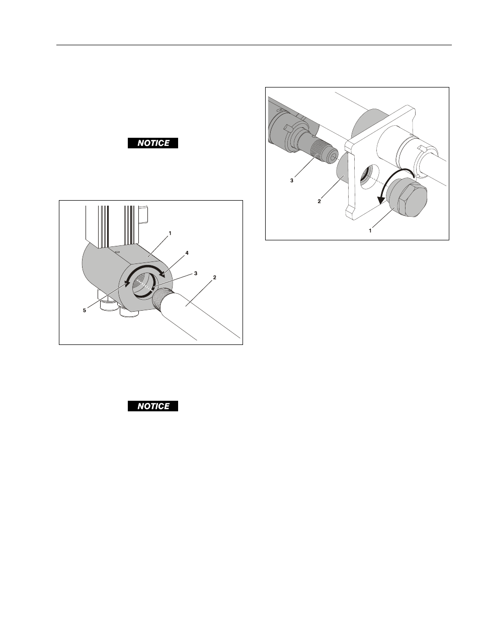
Removing the Valve Block Assembly
PROTECT THE CYLINDER ROD SURFACE. DAMAGE TO THE CYL-
INDER ROD CHROME FINISH DUE TO SCRATCHING, INDENDA-
TION, CHIPPING OR OTHERWISE WILL CAUSE EVENTUAL
G L A N D S E A L F A I L U R E . T H E C Y L I N D E R R O D M U S T B E
REPLACED IF DAMAGED.
1. Wrap the cylinder rod to protect it from damage,
then clamp the cylinder rod into a vise or device to
keep it from turning while removing the valve block
assembly.
2. Using the proper size wrench, (approx. 55mm -
2.165"), turn the valve block assembly counterclock-
wise to remove it from the end of the cylinder rod.
Cylinder #2 and #3 - Removal from Stack
1. Using the proper size wrench, (44mm - 1.732")
remove cylinder #2 rod attach cap by turning the
cap counterclockwise to remove.
2. Once the attach cap is removed from cylinder #2
rod, slide the cylinder #2 and #3 assembly out of
the joint sleeve. Move the cylinder #2 and #3
assembly to a suitable workbench for disassembly.
Figure 6-17. Valve Block - Removal
1. Valve Block
2. Cyl. #1 - Cylinder Rod
3. O-Ring Seal
4. Direction for Removing
5. Direction for Installing
Figure 6-18. Cylinder #2 and #3 Assembly - Removal
1. Rod Attach Cap
2. Cylinder Joint
3. Cyl. #2 and #3 Assem-
bly