Hydraulic cylinder component inspection, Steer cylinder - assembly – JLG 1230ES Service Manual User Manual
Page 44
SECTION 4 - BASE COMPONENTS
4-8
– JLG Lift –
3121222
Hydraulic Cylinder Component Inspection
Cylinder Rod
There should be no scratches or pits deep enough to
catch the fingernail. Pits that go to the base metal are
unacceptable. Scratches that catch the fingernail but are
not to the base metal, less than 0.5 inch long and primarily
in the circumferential direction are acceptable provided
they cannot cut the rod seal. Chrome should be present
over the entire surface of the rod and the lack thereof is
unacceptable. In the event that an unacceptable condition
occurs, the rod should be repaired or replaced.
Cylinder Head (Gland)
Visually inspect the inside bore for scratches or polishing.
Deep scratches are unacceptable. Polishing indicates
uneven loading and when this occurs, the bore should be
checked for out-of-roundness. If out-of-roundness exceed
0.007", this is unacceptable. Check the condition of the
dynamic seals (wiper, rod seals) looking particularly for
metallic particles embedded in the seal surface. It is nor-
mal to cut the static seal on the retaining ring groove upon
disassembly. Remove the rod seal, static o-ring and
backup and rod wiper. Damage to the seal grooves, par-
ticularly on the sealing surfaces, is unacceptable. In the
event that an unacceptable condition occurs, the head
should be replaced.
Piston
Visually inspect the outside surface for scratches or pol-
ishing. Deep scratches are unacceptable. Polishing indi-
cates uneven loading and when this occurs, the diameter
should be checked for out-of-roundness. If out-of-round-
ness exceeds 0.007", this is unacceptable. Check the con-
dition of the dynamic seals and bearings looking
particularly for metallic particles embedded in the bearing
and in the piston seal surface. Remove the seals and
bearings. Damage to the seal grooves, particularly on the
sealing surfaces, is unacceptable. In the event that an
unacceptable condition occurs, the piston should be
replaced.
Tube Assembly
Visually inspect the inside bore for scratches and pits.
There should be no scratches or pits deep enough to
catch the fingernail. Scratches that catch the fingernail but
are less than 0.5 inch long and primarily in the circumfer-
ential direction are acceptable provided they cannot cut
the piston seal. The roughness of the bore should be
between 10 and 20 μ inches RMS. Significant variation
(greater than 8 μ inches difference) are unacceptable. In
the event that an unacceptable condition occurs, the tube
assembly should be repaired or replaced.
Steer Cylinder - Assembly
NOTE: Prior to cylinder assembly, ensure the proper JLG
seal kits are used, see the JLG Parts Manual.
APPLY A LIGHT FILM OF THE HYDRAULIC OIL TO BE USED FOR
OPERATION TO ALL CO MPONENTS TO BE ASSEM BLED,
EXCEPT THE THREADED AREAS WHERE LOCTITE IS TO BE
APPLIED.
1. Load the seals, o’rings, and backing ring onto the
cylinder head (gland).
2. Lubricate the cylinder rod surface with clean hydrau-
lic oil, then slide the cylinder head (gland) assembly
onto the rod.
3. Check that the threads on the cylinder rod and
inside the piston are clean and free of any hydraulic
oil.
4. Apply Loctite #242 to the threads of the cylinder rod
and thread the piston onto the end of the cylinder
rod, tighten piston with the proper spanner wrench
and torque the piston to 260Nm (55 ft. lb.).
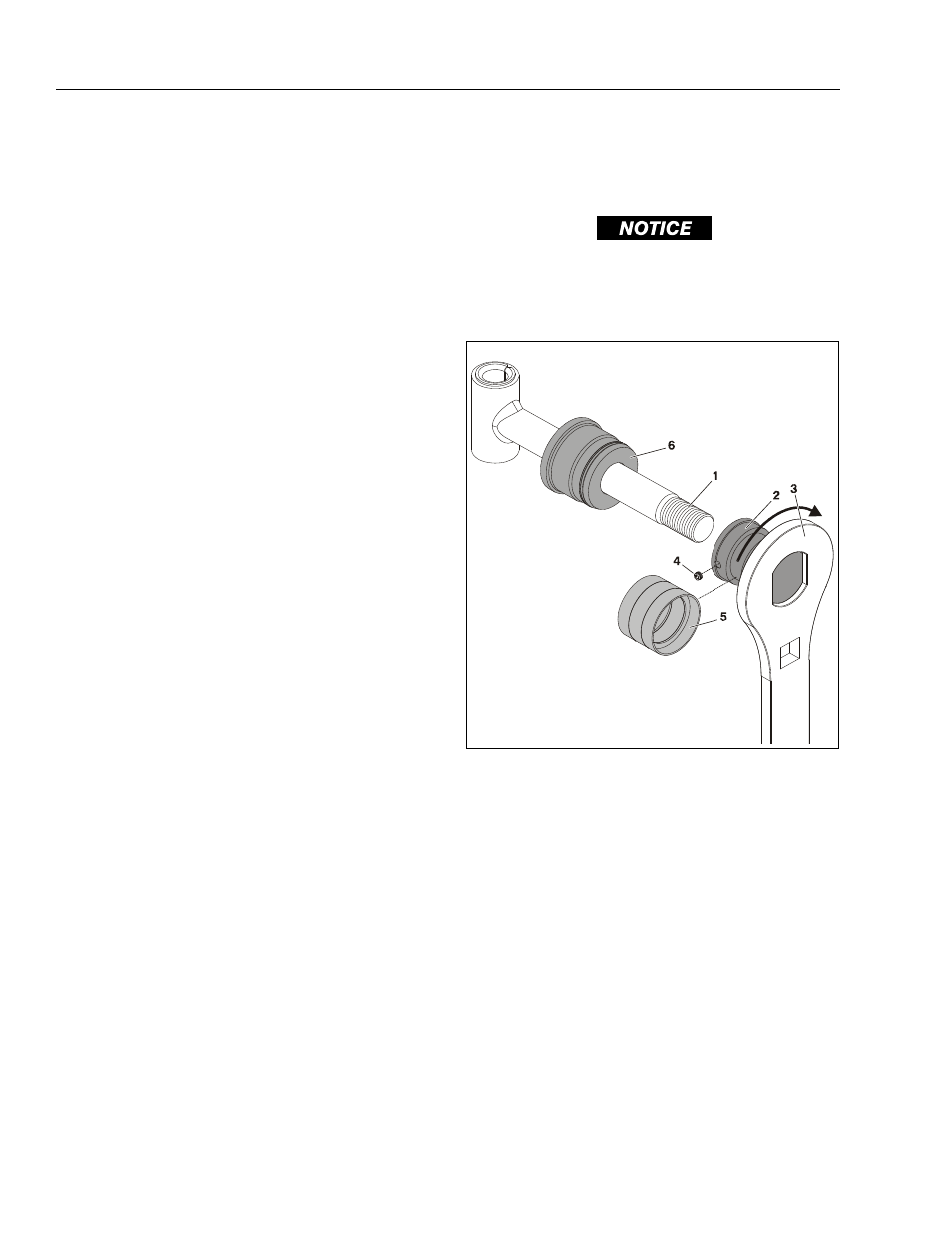
Piston Installation
1. Threaded End of Rod (a)
2. Piston (b)
3. Cylinder Head (Gland)
4. Piston Set Screw (c)
5. Piston (Kban) Seal
NOTE: (a) Apply Loctite #242 on final assembly
(b) Torque piston to 260Nm (55 ft. lb.)
(c) Apply Loctite #222 and torque to 20Nm (5 ft. lb.)